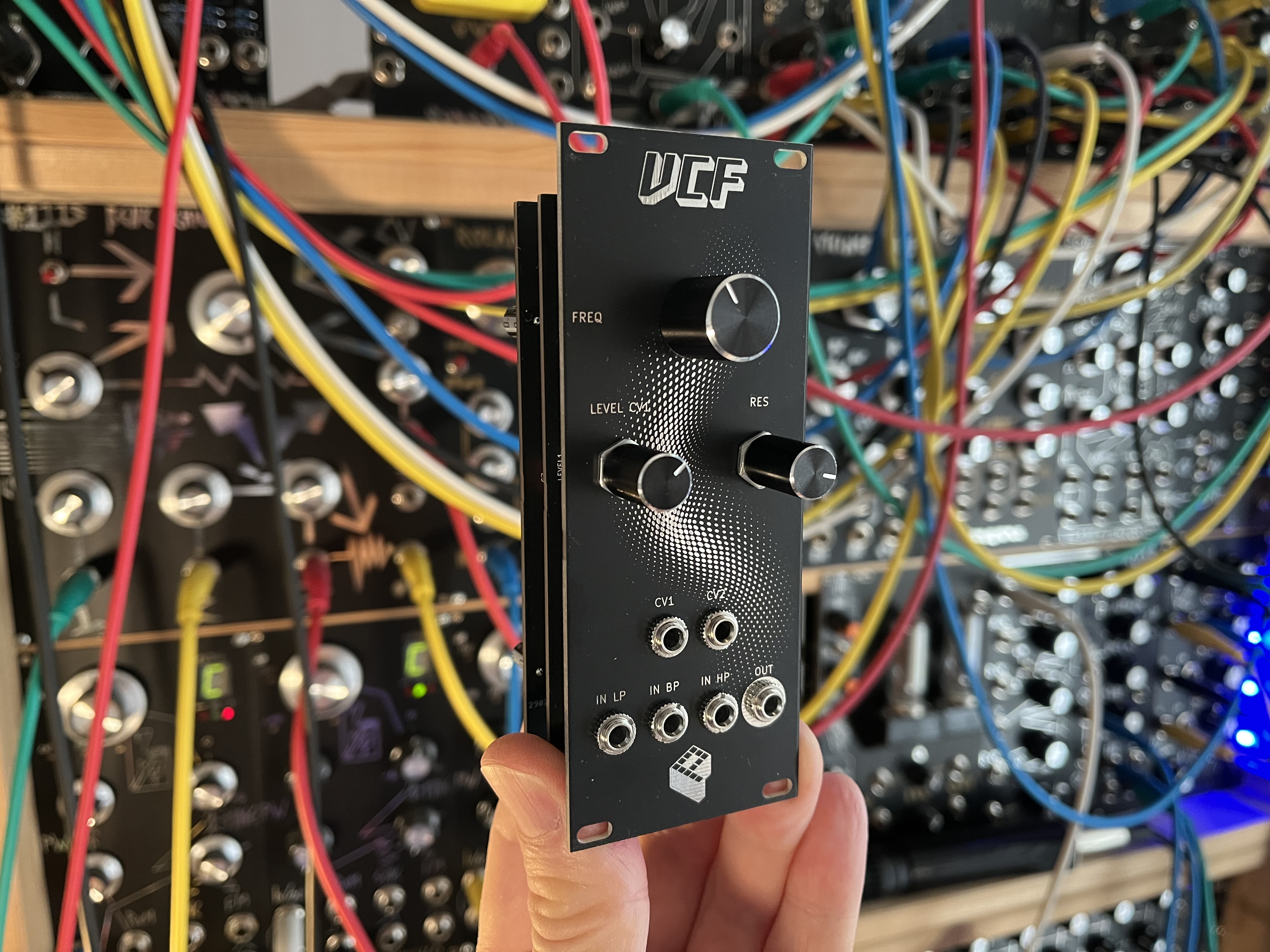
This filter is part of my Eurorack series. The design is based on the Steiner-Parker diode filter, and I stripped it down to a minimal set of components while keeping its characteristic sound. It has controls for frequency cut-off, resonance and CV level. There are distinct inputs for low-pass, band-pass and high-pass, which allow all sorts of filter responses when combining them.
Buy kit or PCBs in my storeKey features#
- voltage controlled diode filter
- inputs for low-pass, band-pass and high-pass response
- controls for frequency, resonance and CV input level
- two CV inputs for controlling the cut-off frequency
- easy to build, all through hole components
- 10 HP
Demo#
How it works#
It is basically an RC-filter circuit where the resistors are replaced by diodes to have voltage control over the filter cut-off frequency. The diodes change resistance when their forward bias voltage is changed by the differential amplifier formed by Q1 and Q2. Inputs are introduced in different places of the circuit to have low-pass, band-pass and high-pass responses. The inputs are buffered and can be combined to achieve different filter responses. There are controls for filter cut-off frequency, resonance and level for one of the CV inputs.
Assembly#
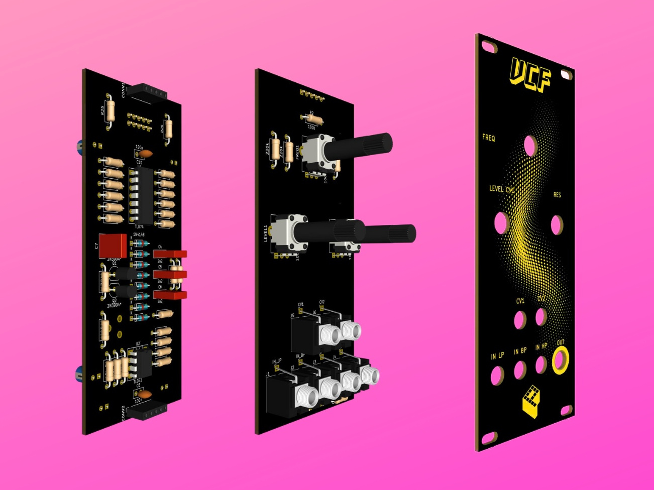
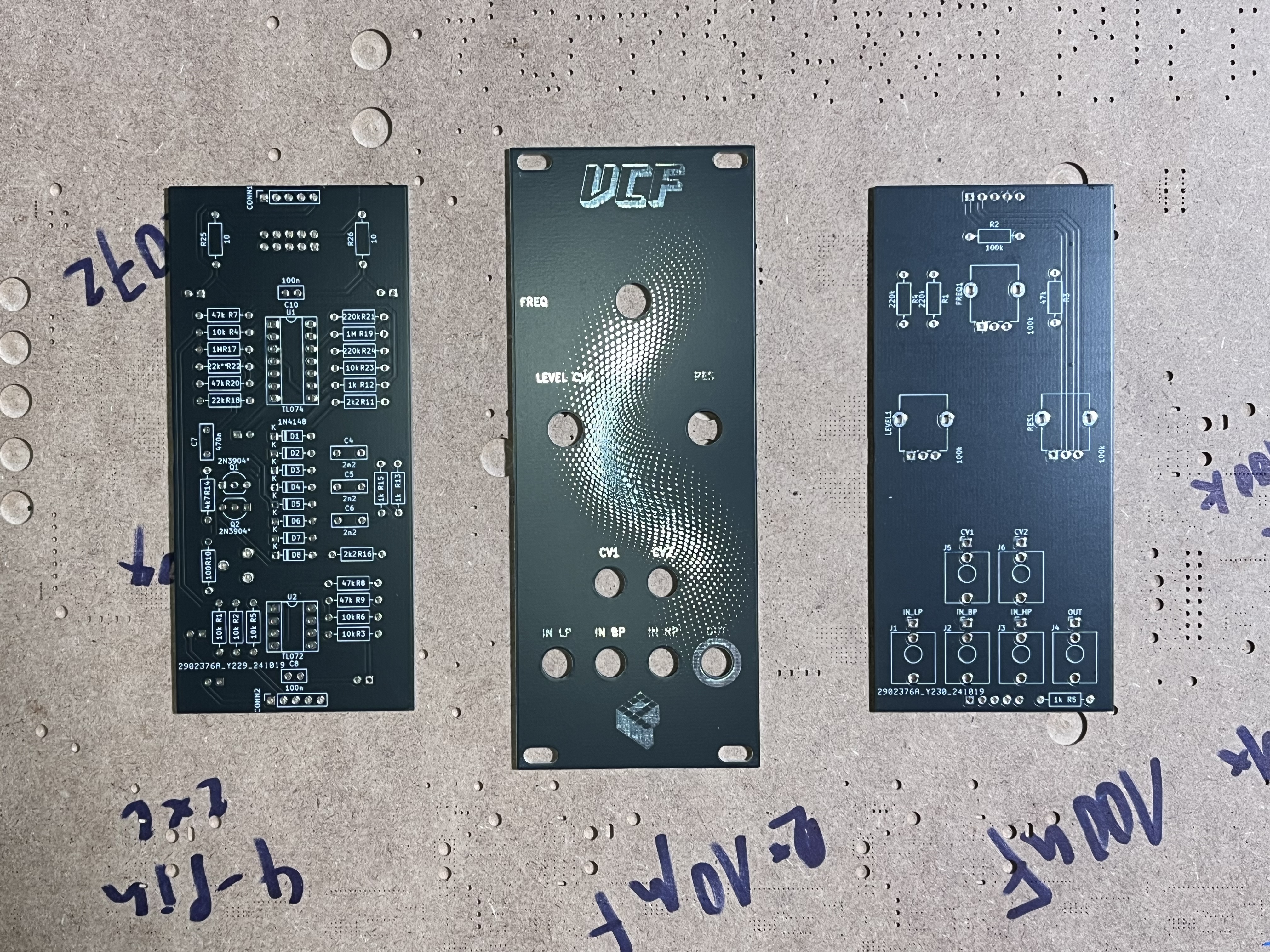
The build is pretty straight forward. The module only consists of through-hole components and is easy to assemble. There are three boards: a front panel, a board for controls/jacks and a board for the circuit.
First, solder all parts on the component board. Keep the jacks and potentiometers for the end. Begin with the components with the lowest profile and work your way up. Screw the jacks and potentiometer to the front panel before soldering them. All components have a fixed designator and a component value printed on the board. Additional information on the parts can be found in the BOM below.
See the Component Basics guide for help identifying parts.
Tuning#
There is a trimmer TRIM1 to adjust the range of the frequency control to your liking. Ideally, connect a signal to the low-pass input and adjust the trimmer until there is no more change in filter response when the frequency control is turned fully clockwise.
The transistors Q1 and Q2 can be matched to have a more accurate filter response, but you might well get away without it.
BOM#
Link to interactive BOM of the component board
| Reference | Value | Footprint | Qty | Description |
|---|---|---|---|---|
| C1,C2,C3,C9 | 10u | Capacitor_THT:CP_Radial_D5.0mm_P2.50mm | 4 | electrolytic |
| C4,C5,C6 | 2n2 | Capacitor_THT:C_Rect_L7.2mm_W2.5mm_P5.00mm_FKS2_FKP2_MKS2_MKP2 | 3 | film |
| C7 | 470n | Capacitor_THT:C_Rect_L7.2mm_W2.5mm_P5.00mm_FKS2_FKP2_MKS2_MKP2 | 1 | film |
| C8,C10 | 100n | Capacitor_THT:C_Disc_D5.0mm_W2.5mm_P2.50mm | 2 | ceramic |
| C11,C12 | 47u | Capacitor_THT:CP_Radial_D5.0mm_P2.50mm | 2 | electrolytic |
| CONN1,CONN2 | ~ | Connector_PinSocket_2.54mm:PinSocket_1x05_P2.54mm_Vertical | 2 | 5-pin socket |
| D1,D2,D3,D4,D5,D6,D7,D8 | 1N4148 | Diode_THT:D_DO-35_SOD27_P7.62mm_Horizontal | 8 | |
| POWER1 | Conn_02x05_Odd_Even | Connector_IDC:IDC-Header_2x05_P2.54mm_Vertical | 1 | IDC 10-pin |
| Q1,Q2 | 2N3904* | Package_TO_SOT_THT:TO-92_Inline_Wide | 2 | |
| R1,R2,R3,R4,R5,R6,R23 | 10k | Resistor_THT:R_Axial_DIN0207_L6.3mm_D2.5mm_P10.16mm_Horizontal | 7 | 1/4W 1% resistor |
| R7,R8,R9,R20 | 47k | Resistor_THT:R_Axial_DIN0207_L6.3mm_D2.5mm_P10.16mm_Horizontal | 4 | 1/4W 1% resistor |
| R10 | 100 | Resistor_THT:R_Axial_DIN0207_L6.3mm_D2.5mm_P10.16mm_Horizontal | 1 | 1/4W 1% resistor |
| R11,R16 | 2k2 | Resistor_THT:R_Axial_DIN0207_L6.3mm_D2.5mm_P10.16mm_Horizontal | 2 | 1/4W 1% resistor |
| R12,R13,R15 | 1k | Resistor_THT:R_Axial_DIN0207_L6.3mm_D2.5mm_P10.16mm_Horizontal | 3 | 1/4W 1% resistor |
| R14 | 4k7 | Resistor_THT:R_Axial_DIN0207_L6.3mm_D2.5mm_P10.16mm_Horizontal | 1 | 1/4W 1% resistor |
| R17,R19 | 1M | Resistor_THT:R_Axial_DIN0207_L6.3mm_D2.5mm_P10.16mm_Horizontal | 2 | 1/4W 1% resistor |
| R18 | 22k | Resistor_THT:R_Axial_DIN0207_L6.3mm_D2.5mm_P10.16mm_Horizontal | 1 | 1/4W 1% resistor |
| R21,R24 | 220k | Resistor_THT:R_Axial_DIN0207_L6.3mm_D2.5mm_P10.16mm_Horizontal | 2 | 1/4W 1% resistor |
| R22 | 22k** | Resistor_THT:R_Axial_DIN0207_L6.3mm_D2.5mm_P10.16mm_Horizontal | 1 | 1/4W 1% resistor |
| R25,R26 | 10 | Resistor_THT:R_Axial_DIN0207_L6.3mm_D2.5mm_P10.16mm_Horizontal | 2 | 1/4W 1% resistor |
| TRIM1 | 2k | Potentiometer_THT:Potentiometer_ACP_CA9-H5_Horizontal | 1 | RM065 trim-potentiometer |
| U1 | TL074 | Package_DIP:DIP-14_W7.62mm_Socket_LongPads | 1 | |
| U2 | TL072 | Package_DIP:DIP-8_W7.62mm_Socket_LongPads | 1 |
* optionally matched transistors
** adjust to change resonance behaviour
Link to interactive BOM of the control board
| Reference | Value | Footprint | Qty | Description |
|---|---|---|---|---|
| CONN1,CONN2 | ~ | Connector_PinHeader_2.54mm:PinHeader_1x05_P2.54mm_Vertical | 2 | 5-pin header |
| FREQ1,LEVEL1,RES1 | 100k | Potentiometer_THT:Potentiometer_Alpha_RD901F-40-00D_Single_Vertical | 3 | linear, vertical, threaded, 6mm |
| J1 | IN_LP | Connector_Audio:Jack_3.5mm_QingPu_WQP-PJ398SM_Vertical_CircularHoles | 1 | Thonkiconn 3.5mm jack sockets |
| J2 | IN_BP | Connector_Audio:Jack_3.5mm_QingPu_WQP-PJ398SM_Vertical_CircularHoles | 1 | Thonkiconn 3.5mm jack sockets |
| J3 | IN_HP | Connector_Audio:Jack_3.5mm_QingPu_WQP-PJ398SM_Vertical_CircularHoles | 1 | Thonkiconn 3.5mm jack sockets |
| J4 | OUT | Connector_Audio:Jack_3.5mm_QingPu_WQP-PJ398SM_Vertical_CircularHoles | 1 | Thonkiconn 3.5mm jack sockets |
| J5 | CV1 | Connector_Audio:Jack_3.5mm_QingPu_WQP-PJ398SM_Vertical_CircularHoles | 1 | Thonkiconn 3.5mm jack sockets |
| J6 | CV2 | Connector_Audio:Jack_3.5mm_QingPu_WQP-PJ398SM_Vertical_CircularHoles | 1 | Thonkiconn 3.5mm jack sockets |
| R1,R4 | 220k | Resistor_THT:R_Axial_DIN0207_L6.3mm_D2.5mm_P10.16mm_Horizontal | 2 | 1/4W 1% resistor |
| R2 | 100k | Resistor_THT:R_Axial_DIN0207_L6.3mm_D2.5mm_P10.16mm_Horizontal | 1 | 1/4W 1% resistor |
| R3 | 47k | Resistor_THT:R_Axial_DIN0207_L6.3mm_D2.5mm_P10.16mm_Horizontal | 1 | 1/4W 1% resistor |
| R5 | 1k | Resistor_THT:R_Axial_DIN0207_L6.3mm_D2.5mm_P10.16mm_Horizontal | 1 | 1/4W 1% resistor |
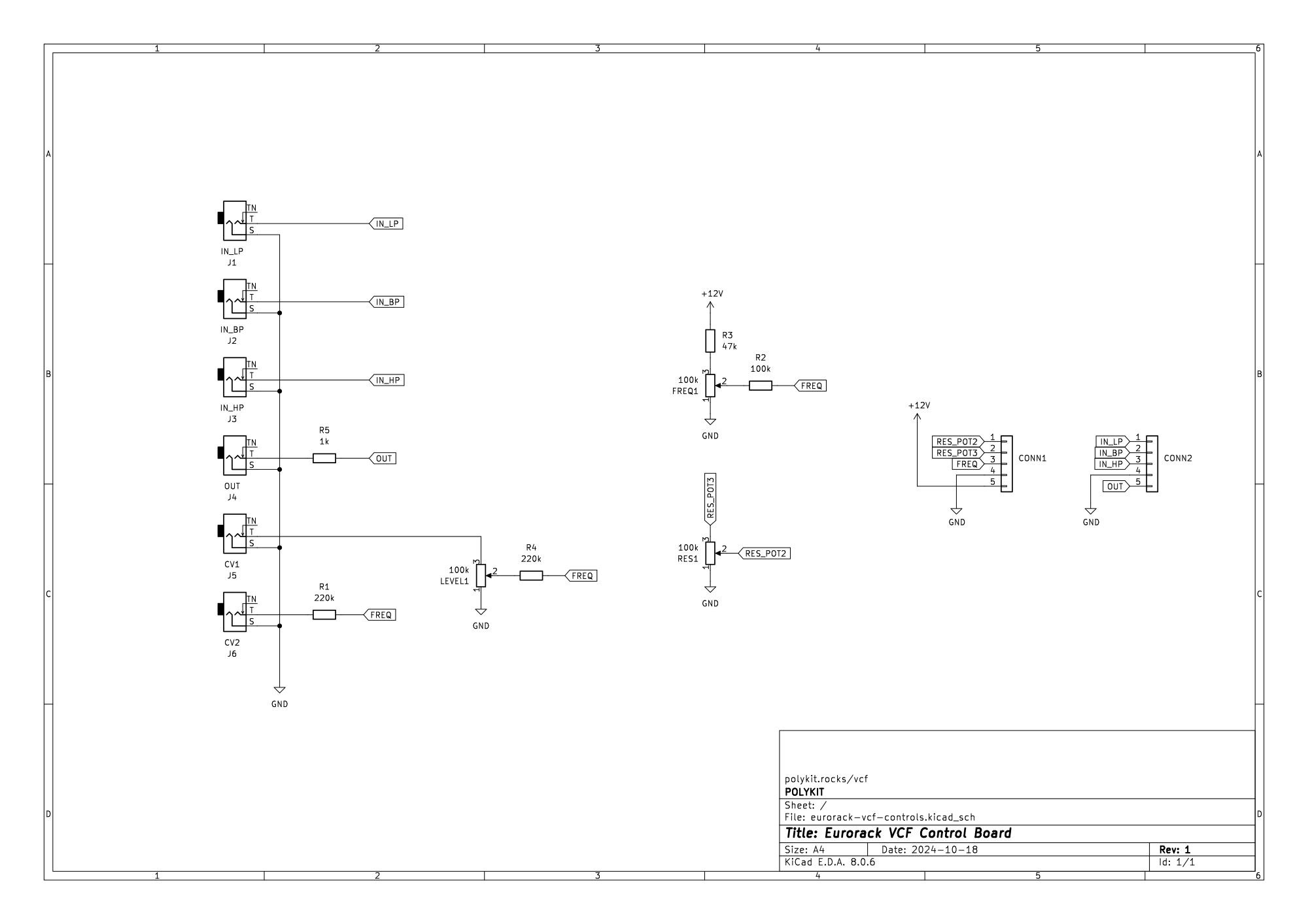
Schematics#

References#
https://yusynth.net/Modular/EN/STEINERVCF/index-V2.html
https://www.yusynth.net/archives/ElectronicDesign/N-Steiner-VCF-1974.pdf
https://sdiy.info/wiki/CGS_Steiner_voltage_controlled_HP,_LP_and_BP_filter