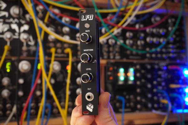
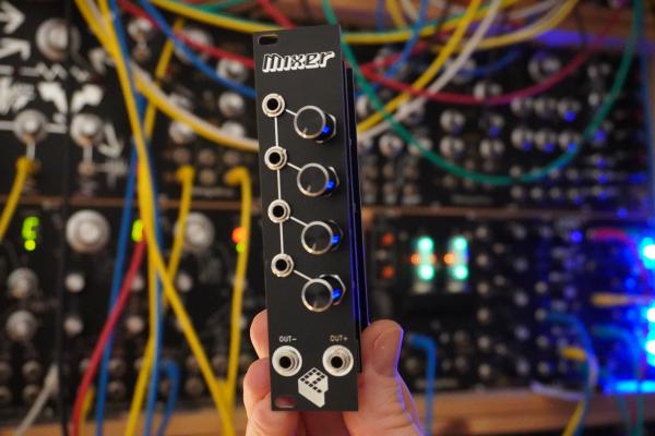
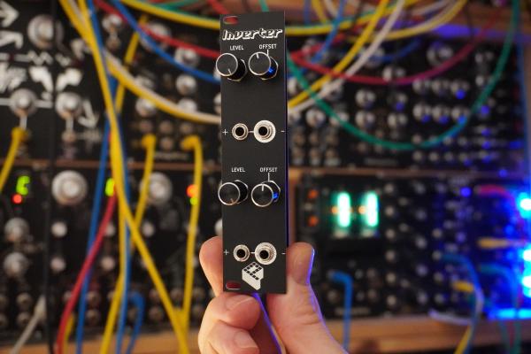
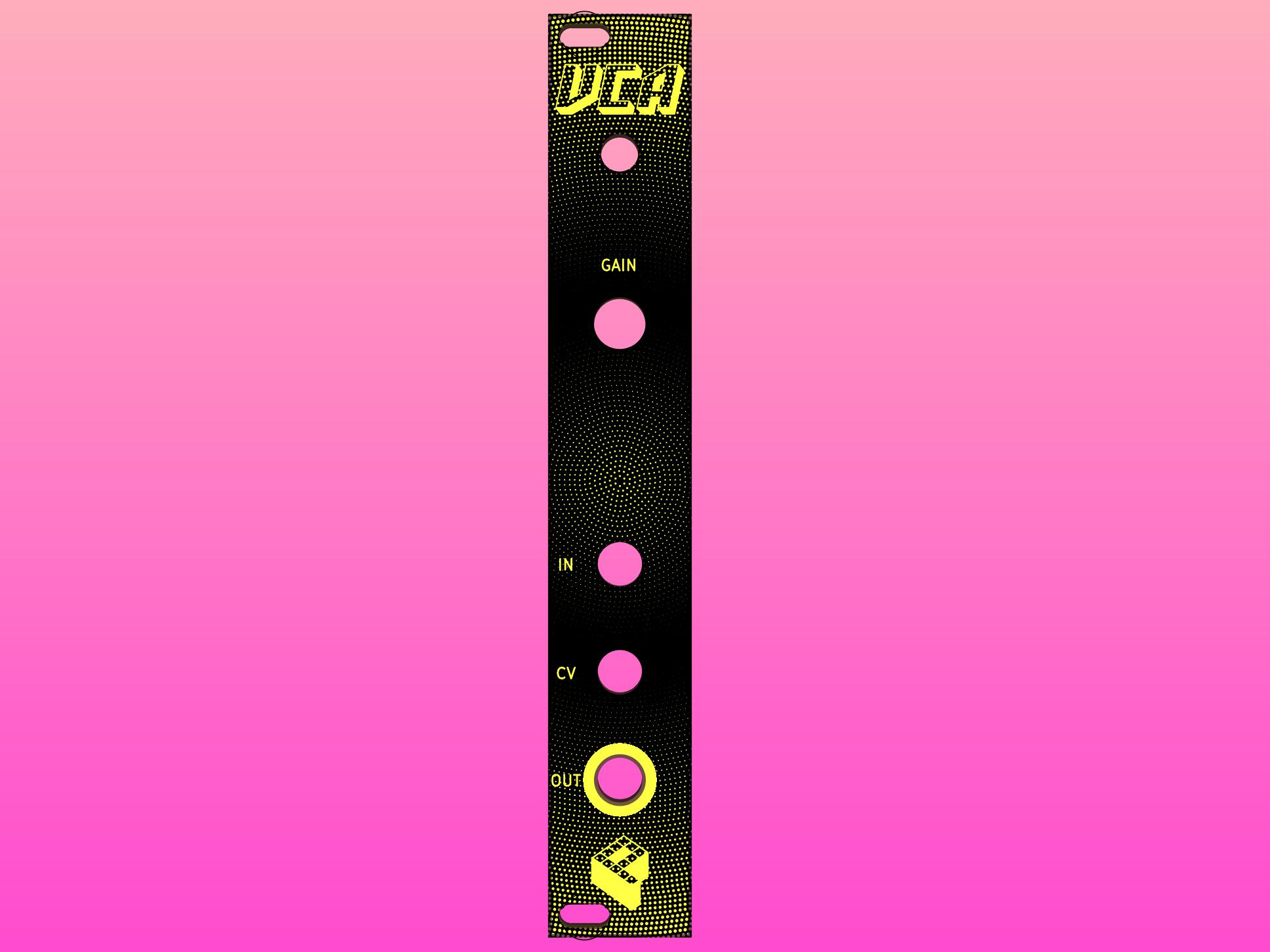
This module is part of my Eurorack series. It’s a voltage controlled amplifier made out of a minimal set of components. It works great in conjunction with an envelope generator and makes your synth sound more natural. There are a lot of applications like shaping different sounds, side-chaining and so on.
Buy kit or PCBs in my storeKey features#
- voltage controlled amplifier
- signal input and output, CV
- gain control
- signal LED
- easy to build, all through hole components
- 4HP
How it works#
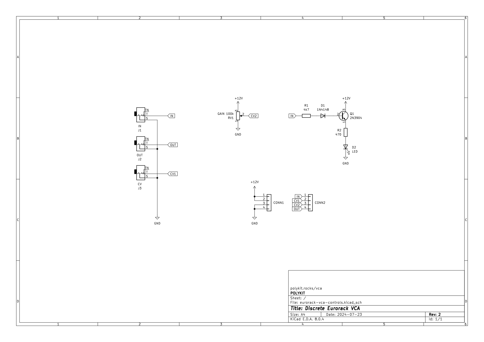
The heart of the VCA is a long-tailed pair made out of two transistors. It’s a differential amplifier which can be voltage controlled through a third transistor. It has an input and output for the signal and a CV input for controlling the amount of amplification. There is a gain pot which is also controlling the amplification of the VCA.
Assembly#
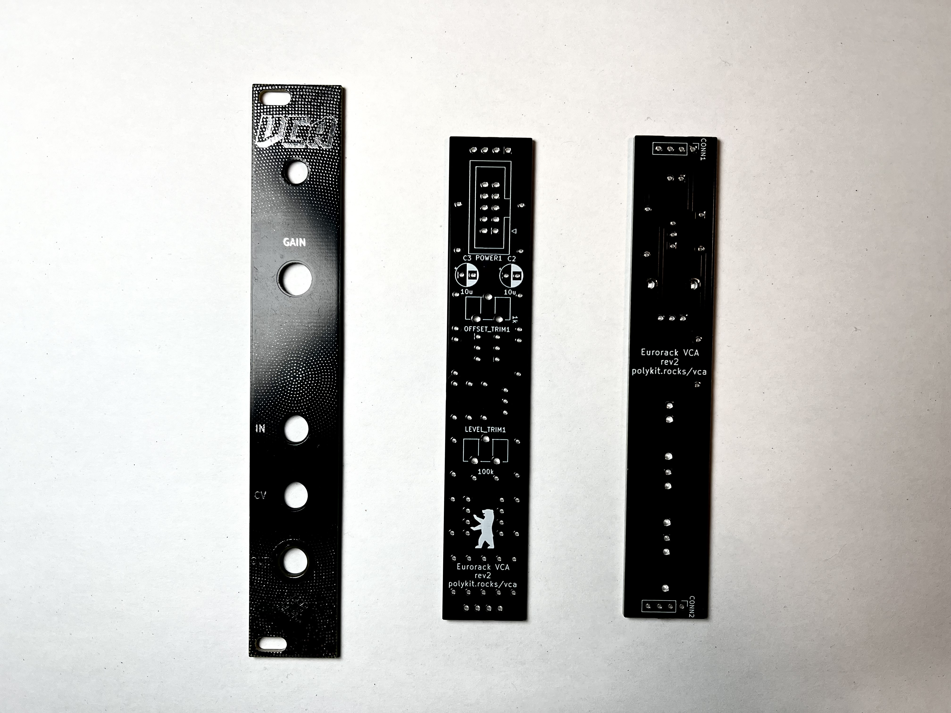
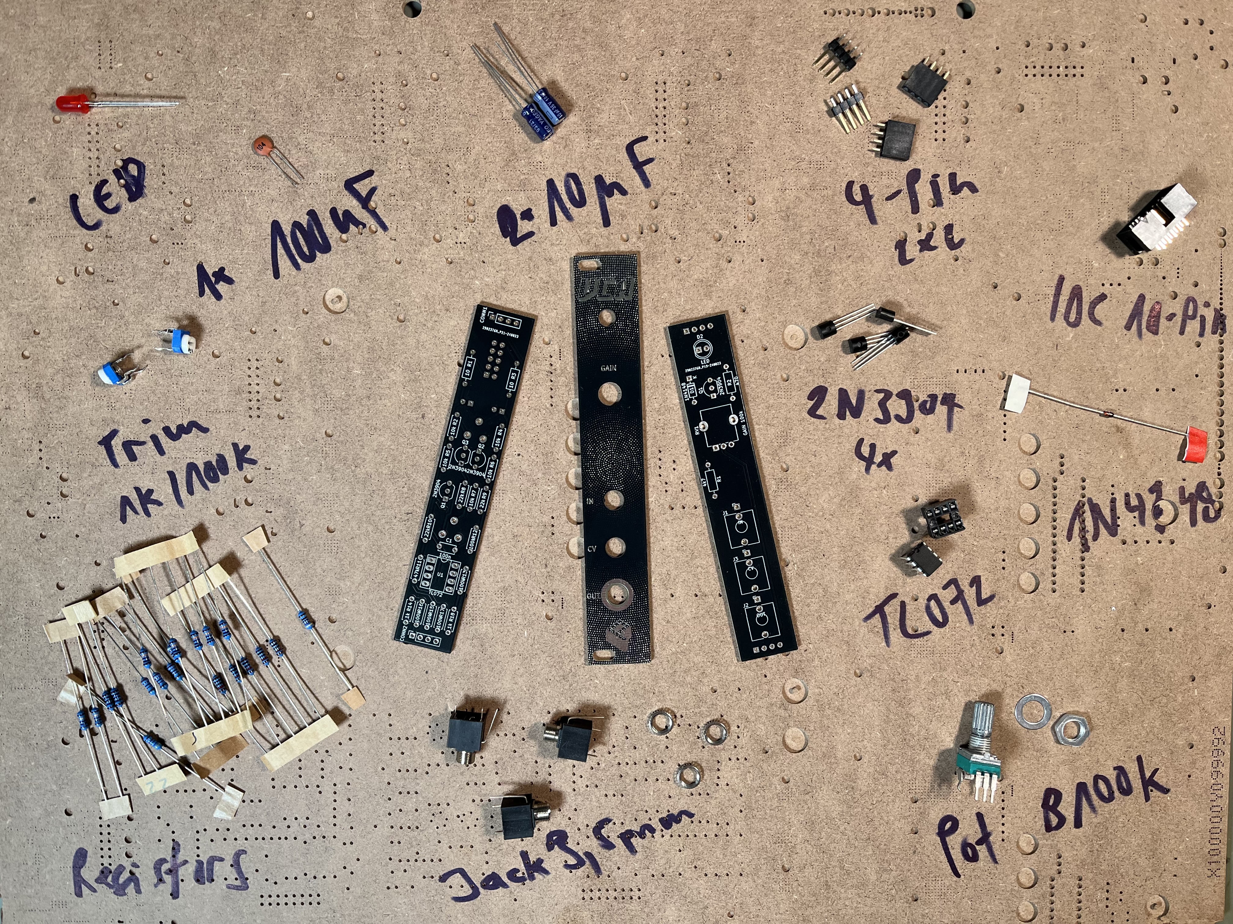
The build is pretty straight forward. The module only consists of through-hole components and is easy to assemble. There are three boards: a front panel, a board for controls/jacks and a board for the circuit.
First, solder all parts on the component board. Keep the jacks and potentiometers for the end. Begin with the components with the lowest profile and work your way up. Screw the jacks and potentiometer to the front panel before soldering them. All components have a fixed designator and a component value printed on the board. Additional information on the parts can be found in the BOM below.
See the Component Basics guide for help identifying parts.
Transistor Matching#
You might get away without matching of the transistors Q2 and Q3 on the main component board. There is a trimpot OFFSET to adjust misalignment of the differential amplifier, see tuning section. But for even better results there is a not too complicated method to find matching pairs in a bunch of transistors, see links below. I have good results using two 9V block batteries as a dual power source and a fan to keep the temperature stable.
Tuning#
Connect a signal (e.g. sine wave) to the VCA, turn the gain knob to zero and adjust the LEVEL trim pot. Start from the centre position until you can’t hear the signal any more.
For adjusting the offset you ideally need an oscilloscope. Connect a signal to the VCA, adjust the gain until the amplitude of input and output signal are equal. Now adjust the OFFSET trimmer until both signals match. If you don’t have an oscilloscope you can do this by listening to it and compare both input and output signal. Start from the centre position of the trimpot.
BOM#
Link to interactive BOM of the component board
| Reference | Value | Footprint | Qty | Description |
|---|---|---|---|---|
| C1 | 100n | Capacitor_THT:C_Disc_D5.0mm_W2.5mm_P5.00mm | 1 | ceramic |
| C2,C3 | 10u | Capacitor_THT:CP_Radial_D5.0mm_P2.50mm | 2 | electrolytic |
| CONN1,CONN2 | Conn_01x04 | Connector_PinSocket_2.54mm:PinSocket_1x04_P2.54mm_Vertical | 2 | Pin socket, 4-pin |
| LEVEL_TRIM1 | TRIM 100k | Potentiometer_THT:Potentiometer_ACP_CA9-H5_Horizontal | 1 | Trimpot |
| OFFSET_TRIM1 | TRIM 1k | Potentiometer_THT:Potentiometer_ACP_CA9-H5_Horizontal | 1 | Trimpot |
| POWER1 | Conn_02x05_Odd_Even | Connector_IDC:IDC-Header_2x05_P2.54mm_Vertical | 1 | IDC 10-pin connector |
| Q1,Q2,Q3 | 2N3904 | Package_TO_SOT_THT:TO-92_Inline_Wide | 3 | |
| R1,R3 | 10 | Resistor_THT:R_Axial_DIN0207_L6.3mm_D2.5mm_P10.16mm_Horizontal | 2 | 1/4W 1% resistor |
| R2,R4,R5,R6,R7 | 10k | Resistor_THT:R_Axial_DIN0207_L6.3mm_D2.5mm_P7.62mm_Horizontal | 5 | 1/4W 1% resistor |
| R8,R9,R10 | 22k | Resistor_THT:R_Axial_DIN0207_L6.3mm_D2.5mm_P7.62mm_Horizontal | 3 | 1/4W 1% resistor |
| R11 | 47k | Resistor_THT:R_Axial_DIN0207_L6.3mm_D2.5mm_P7.62mm_Horizontal | 1 | 1/4W 1% resistor |
| R12,R13,R15,R16,R17 | 100k | Resistor_THT:R_Axial_DIN0207_L6.3mm_D2.5mm_P7.62mm_Horizontal | 5 | 1/4W 1% resistor |
| R14,R18 | 1k | Resistor_THT:R_Axial_DIN0207_L6.3mm_D2.5mm_P7.62mm_Horizontal | 2 | 1/4W 1% resistor |
| U1 | TL072 | Package_DIP:DIP-8_W7.62mm_Socket_LongPads | 1 |
Link to interactive BOM of the control board
| Reference | Value | Footprint | Qty | Description |
|---|---|---|---|---|
| CONN1,CONN2 | Conn_01x04 | Connector_PinHeader_2.54mm:PinHeader_1x04_P2.54mm_Vertical | 2 | Generic connector, single row, 01x04, script generated (kicad-library-utils/schlib/autogen/connector/) |
| D1 | 1N4148 | Diode_THT:D_DO-35_SOD27_P7.62mm_Horizontal | 1 | 100V 0.15A standard switching diode, DO-35 |
| D2 | LED | LED_THT:LED_D5.0mm | 1 | 5mm LED |
| J1 | IN | Connector_Audio:Jack_3.5mm_QingPu_WQP-PJ398SM_Vertical_CircularHoles | 1 | Thonkiconn 3.5mm jack sockets |
| J2 | OUT | Connector_Audio:Jack_3.5mm_QingPu_WQP-PJ398SM_Vertical_CircularHoles | 1 | Thonkiconn 3.5mm jack sockets |
| J3 | CV | Connector_Audio:Jack_3.5mm_QingPu_WQP-PJ398SM_Vertical_CircularHoles | 1 | Thonkiconn 3.5mm jack sockets |
| Q1 | 2N3904 | Package_TO_SOT_THT:TO-92_Inline_Wide | 1 | NPN transistor |
| R1 | 4k7 | Resistor_THT:R_Axial_DIN0207_L6.3mm_D2.5mm_P10.16mm_Horizontal | 1 | 1/4W 1% resistor |
| R2 | 470 | Resistor_THT:R_Axial_DIN0207_L6.3mm_D2.5mm_P10.16mm_Horizontal | 1 | 1/4W 1% resistor |
| RV1 | GAIN 100k | Potentiometer_THT:Potentiometer_Alpha_RD901F-40-00D_Single_Vertical | 1 | linear, vertical, threaded, 6mm |
Schematics#

References#
https://yusynth.net/Modular/EN/VCA/index.html
https://kassu2000.blogspot.com/2015/10/vca.html
https://www.dragonflyalley.com/synth/images/TransistorMatching/ianFritz-transmat0011_144.pdf
https://kassu2000.blogspot.com/2015/10/transistor-matching.html