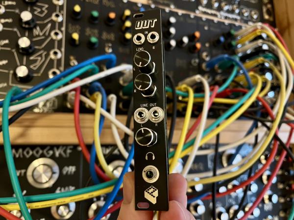
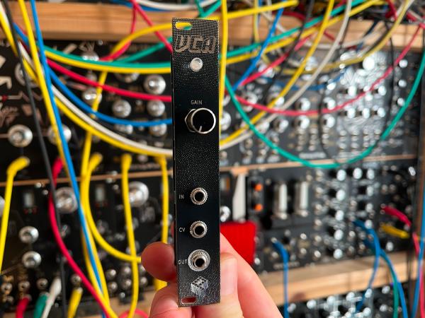
This spring reverb module is part of my Eurorack series. It drives a reverb tank and has two inputs, control for dry/wet to blend between original and processed signal, and a resonance control for feedback.
Buy kit or PCBs in my storeKey features#
- spring reverb driver
- two inputs
- dry/wet control
- resonance control
- PCBs/panel and full DIY kits available
- easy to assemble
- 6 HP


How it works#
Two input signals are mixed together, and there is a dry/wet control to blend between the original and processed signal. The reverb output signal is fed back to the input and can be controlled by the resonance pot.
Two op-amps are connected in parallel to drive the reverb tank. I’m using a NE5532 op-amp, which has a higher output power than the TL074 to deliver enough current.
Using two electrolytic capacitors back-to-back (C2/C3 and C7/C8) is to have a non-polarized capacitor with half the value, around 10uF in this case.
You need a separate reverb tank; it is not part of the kit. This module is well tested with the Accutronics AMC2BF3/Intellijel small reverb tank but should work with any tank that has an input impedance of 150 ohms or higher. Make sure that the input coil is not grounded to the tanks casing, or it won’t work. There are two 2-pin Molex connectors to connect the tank to the module.
R9 can be adjusted to change the gain of the amplifier’s recovery circuit, a lower value give a lower gain and resonance.
Assembly#
The build is pretty straight-forward. The module only consists of through-hole components and is easy to assemble. There are three boards: a front panel, a board for controls/jacks, and a board for the circuit.
First, solder all parts on the component board. Keep the jacks and potentiometers for the end. Begin with the components with the lowest profile and work your way up. Screw the jacks and potentiometer to the front panel before soldering them. All components have a fixed designator and a component value printed on the board. Additional information on the parts can be found in the BOM below.
See the Component Basics guide for help identifying parts.
BOM#
Link to interactive BOM of the component board
| Reference | Value | Footprint | Qty | Description |
|---|---|---|---|---|
| C1 | 100n | Capacitor_THT:C_Rect_L7.2mm_W2.5mm_P5.00mm_FKS2_FKP2_MKS2_MKP2 | 1 | Film |
| C2,C3,C7,C8 | 22u | Capacitor_THT:CP_Radial_D5.0mm_P2.50mm | 4 | Electrolytic |
| C4 | 1n | Capacitor_THT:C_Rect_L7.2mm_W2.5mm_P5.00mm_FKS2_FKP2_MKS2_MKP2 | 1 | Film |
| C5,C10 | 100n | Capacitor_THT:C_Disc_D5.0mm_W2.5mm_P2.50mm | 2 | Ceramic |
| C6,C11 | 10u | Capacitor_THT:CP_Radial_D5.0mm_P2.50mm | 2 | Electrolytic |
| C9 | 1n | Capacitor_THT:C_Disc_D5.0mm_W2.5mm_P2.50mm | 1 | Ceramic |
| CONN1,CONN2 | Conn_01x04 | Connector_PinSocket_2.54mm:PinSocket_1x04_P2.54mm_Vertical | 2 | 4-pin socket, 2.54mm |
| POWER1 | Conn_02x05_Odd_Even | Connector_IDC:IDC-Header_2x05_P2.54mm_Vertical | 1 | IDC 10-pin power connector |
| R1 | 2k2 | Resistor_THT:R_Axial_DIN0207_L6.3mm_D2.5mm_P10.16mm_Horizontal | 1 | 1/4W 1% resistor |
| R2,R5,R10,R11 | 10 | Resistor_THT:R_Axial_DIN0207_L6.3mm_D2.5mm_P10.16mm_Horizontal | 4 | 1/4W 1% resistor |
| R3,R7,R8,R17,R18 | 100k | Resistor_THT:R_Axial_DIN0207_L6.3mm_D2.5mm_P10.16mm_Horizontal | 5 | 1/4W 1% resistor |
| R4,R13 | 10k | Resistor_THT:R_Axial_DIN0207_L6.3mm_D2.5mm_P10.16mm_Horizontal | 2 | 1/4W 1% resistor |
| R6,R14 | 220 | Resistor_THT:R_Axial_DIN0207_L6.3mm_D2.5mm_P10.16mm_Horizontal | 2 | 1/4W 1% resistor |
| R9 | 22k | Resistor_THT:R_Axial_DIN0207_L6.3mm_D2.5mm_P10.16mm_Horizontal | 1 | 1/4W 1% resistor |
| REVERB_IN1,REVERB_OUT1 | Conn_01x02 | Connector_Molex:Molex_KK-254_AE-6410-02A_1x02_P2.54mm_Vertical | 2 | 2-pin Molex connector, 2.54mm |
| U1 | TL074 | Package_DIP:DIP-14_W7.62mm_Socket_LongPads | 1 | Quad operational amplifier, DIP-14 |
| U2 | NE5532 | Package_DIP:DIP-8_W7.62mm_Socket_LongPads | 1 | Dual operational amplifier, DIP-8 |
Link to interactive BOM of the control board
| Reference | Value | Footprint | Qty | Description |
|---|---|---|---|---|
| CONN1,CONN2 | Conn_01x04 | Connector_PinHeader_2.54mm:PinHeader_1x04_P2.54mm_Vertical | 2 | 4-pin header, 2.54mm |
| DRY_WET1,RES1 | 100k | Potentiometer_THT:Potentiometer_Alpha_RD901F-40-00D_Single_Vertical | 2 | Linear, vertical, threaded, 6mm |
| J1 | OUT | Connector_Audio:Jack_3.5mm_QingPu_WQP-PJ398SM_Vertical_CircularHoles | 1 | Mono Thonkiconn 3.5mm jack sockets |
| J2 | IN1 | Connector_Audio:Jack_3.5mm_QingPu_WQP-PJ398SM_Vertical_CircularHoles | 1 | Mono Thonkiconn 3.5mm jack sockets |
| J3 | IN2 | Connector_Audio:Jack_3.5mm_QingPu_WQP-PJ398SM_Vertical_CircularHoles | 1 | Mono Thonkiconn 3.5mm jack sockets |
| R1 | 1k | Resistor_THT:R_Axial_DIN0207_L6.3mm_D2.5mm_P10.16mm_Horizontal | 1 | 1/4W 1% resistor |
| R2,R3,R4 | 100k | Resistor_THT:R_Axial_DIN0207_L6.3mm_D2.5mm_P10.16mm_Horizontal | 3 | 1/4W 1% resistor |
Schematics#


Changelog#
rev2: Change R9 from 10k to 22k