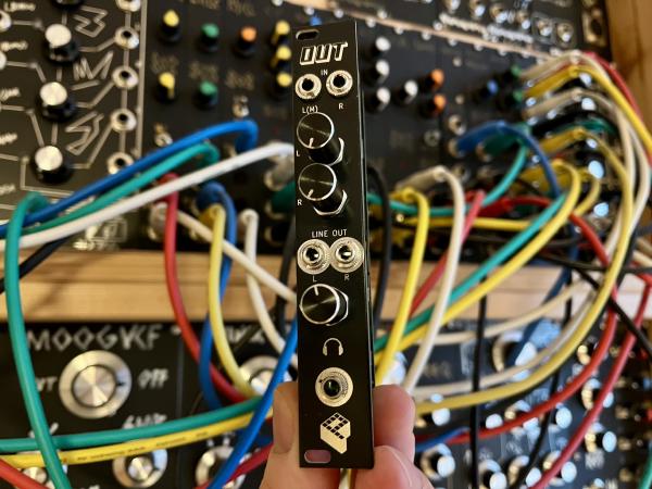
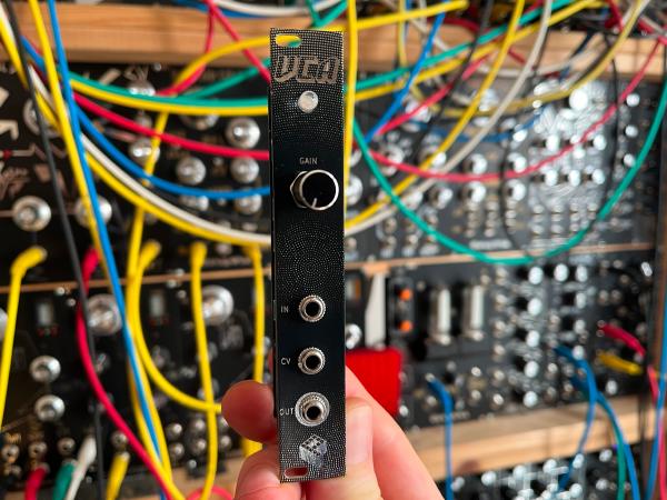
This Eurorack ring modulator allows the multiplication/amplitude modulation of two signals. There are two center-tapped mini transformers and a ring of four diodes, which form this classic analog circuit to create bell-like or metallic sounds. The inputs and output are buffered.
Buy kit or PCBs in my storeKey features#
- ring modulator
- multiplication/amplitude modulation of two signals
- attenuators on the inputs
- easy to assemble
- 4 HP


How it works#
There are two inputs: the modulating signal (A) and the carrier signal (B).
The output signal contains both the sum and the difference of the input signals.
That means we have two sidebands in the output signal: A + B and A - B.
E.g., two sine waves with the frequencies of 400 Hz and 300 Hz would lead to two sidebands with 700 Hz and 100 Hz.
The output signal very much differs from the input signals and can produce an inharmonic, bell-like or metallic effect.
Ideally, the frequency of the carrier signal is much higher than the modulating signal.
The heart of the ring modulator are two SMD transformers, which are center-tapped on one of the windings.
Four BAT48 Schottky diodes with a low forward voltage form the diode ring.
All signals are buffered by an op-amp and there are two potentiometers to attenuate the input signals.
The output signal is amplified in op-amp U1C, adjust R3 to change its output gain.
The diode pairs D1/D4 and D2/D3 basically act as switches and conduct depending on whether the carrier signal is positive or negative. When there is no modulating signal, the carrier signal is cancelled out in the split windings of the transformers, and there is no output signal. When there is a signal applied on the modulating input, it brings imbalance to the cancellation, and a third diode is conducting. Depending on whether the modulating and carrier signals are negative or positive, a changing current is inducted in the transformer’s T2 output winding, leading to the multiplication effect.
Assembly#
The build is pretty straight-forward. The module only consists of through-hole components and is easy to assemble. There are three boards: a front panel, a board for controls/jacks, and a board for the circuit.
First, solder all parts on the component board. Keep the jacks and potentiometers for the end. Begin with the components with the lowest profile and work your way up. Screw the jacks and potentiometer to the front panel before soldering them. All components have a fixed designator and a component value printed on the board. Additional information on the parts can be found in the BOM below.
See the Component Basics guide for help identifying parts.
BOM#
Link to interactive BOM of the component board
| Reference | Value | Footprint | Qty | Description |
|---|---|---|---|---|
| C1 | 100n | Capacitor_THT:C_Disc_D5.0mm_W2.5mm_P2.50mm | 1 | Ceramic |
| C2,C3 | 10u | Capacitor_THT:CP_Radial_D5.0mm_P2.50mm | 2 | Electrolytic |
| CONN1,CONN2 | Conn_01x04 | Connector_PinSocket_2.54mm:PinSocket_1x04_P2.54mm_Vertical | 2 | Generic connector, single row, 01x04, script generated (kicad-library-utils/schlib/autogen/connector/) |
| D1,D2,D3,D4 | BAT48RL | Diode_THT:D_DO-35_SOD27_P7.62mm_Horizontal | 4 | 40V 0.35A Small Signal Schottky Diode, DO-35 |
| POWER1 | Conn_02x05_Odd_Even | Connector_IDC:IDC-Header_2x05_P2.54mm_Vertical | 1 | IDC 10-pin |
| R1,R2 | 470 | Resistor_THT:R_Axial_DIN0207_L6.3mm_D2.5mm_P10.16mm_Horizontal | 2 | Resistor |
| R3 | 10k | Resistor_THT:R_Axial_DIN0207_L6.3mm_D2.5mm_P10.16mm_Horizontal | 1 | Resistor |
| R4,R5,R6 | 100k | Resistor_THT:R_Axial_DIN0207_L6.3mm_D2.5mm_P10.16mm_Horizontal | 3 | Resistor |
| R7,R8 | 10 | Resistor_THT:R_Axial_DIN0207_L6.3mm_D2.5mm_P10.16mm_Horizontal | 2 | 1/4W 1% resistor |
| T1,T2 | Transformer_ED8_5P | transformer-ed8-5pin:Transformer_ED8_5-Lead_10.5x8mm_P5mm | 2 | ED8 audio transformer, single primary, split secondary |
| U1 | TL074 | Package_DIP:DIP-14_W7.62mm_Socket_LongPads | 1 | Quad Low-Noise JFET-Input Operational Amplifiers, DIP-14/SOIC-14 |
Link to interactive BOM of the control board
| Reference | Value | Footprint | Qty | Description |
|---|---|---|---|---|
| CONN1,CONN2 | Conn_01x04 | Connector_PinHeader_2.54mm:PinHeader_1x04_P2.54mm_Vertical | 2 | Generic connector, single row, 01x04, script generated (kicad-library-utils/schlib/autogen/connector/) |
| J1 | IN_A | Connector_Audio:Jack_3.5mm_QingPu_WQP-PJ398SM_Vertical_CircularHoles | 1 | Mono Thonkiconn 3.5mm jack sockets |
| J2 | IN_B | Connector_Audio:Jack_3.5mm_QingPu_WQP-PJ398SM_Vertical_CircularHoles | 1 | Mono Thonkiconn 3.5mm jack sockets |
| J3 | OUT | Connector_Audio:Jack_3.5mm_QingPu_WQP-PJ398SM_Vertical_CircularHoles | 1 | Mono Thonkiconn 3.5mm jack sockets |
| R1,R2,R3 | 1k | Resistor_THT:R_Axial_DIN0207_L6.3mm_D2.5mm_P10.16mm_Horizontal | 3 | 1/4W 1% resistor |
| VOL_A1,VOL_B1 | 100k | Potentiometer_THT:Potentiometer_Alpha_RD901F-40-00D_Single_Vertical | 2 | linear, vertical, threaded, 6mm |
Schematics#


References#
https://www.perfectcircuit.com/signal/ring-modulators
https://wiki.analog.com/university/courses/electronics/electronics_lab_diode_ring_modulator