This Arduino based module let’s you quantize and hold a given control voltage. There are controls for selecting different scales and transposing a note. The module can either continuously quantize a given voltage or hold it when triggered. It uses a 12-bit digital-to-analog converter (DAC) and the software is open-source, so you can adjust it to your liking. It is a great companion for sequencers with unquantized outputs or for quantizing other voltage sources.
Perfect companion for the Sequencer.
Buy kit or PCBs in my storeKey features#
- Quantizer
- Arduino based, open-source software
- Scale mode control, also per CV
- Pass-through mode without quantizing (DAC precision)
- Control for transposing a note -24 to +24 semitones, also per CV
- Trigger input for holding a voltage
- Gate output for voltage changes in continuous mode
- CV input
0-5V - CV output
0-7V(1V/oct) - 4HP wide


How it works#
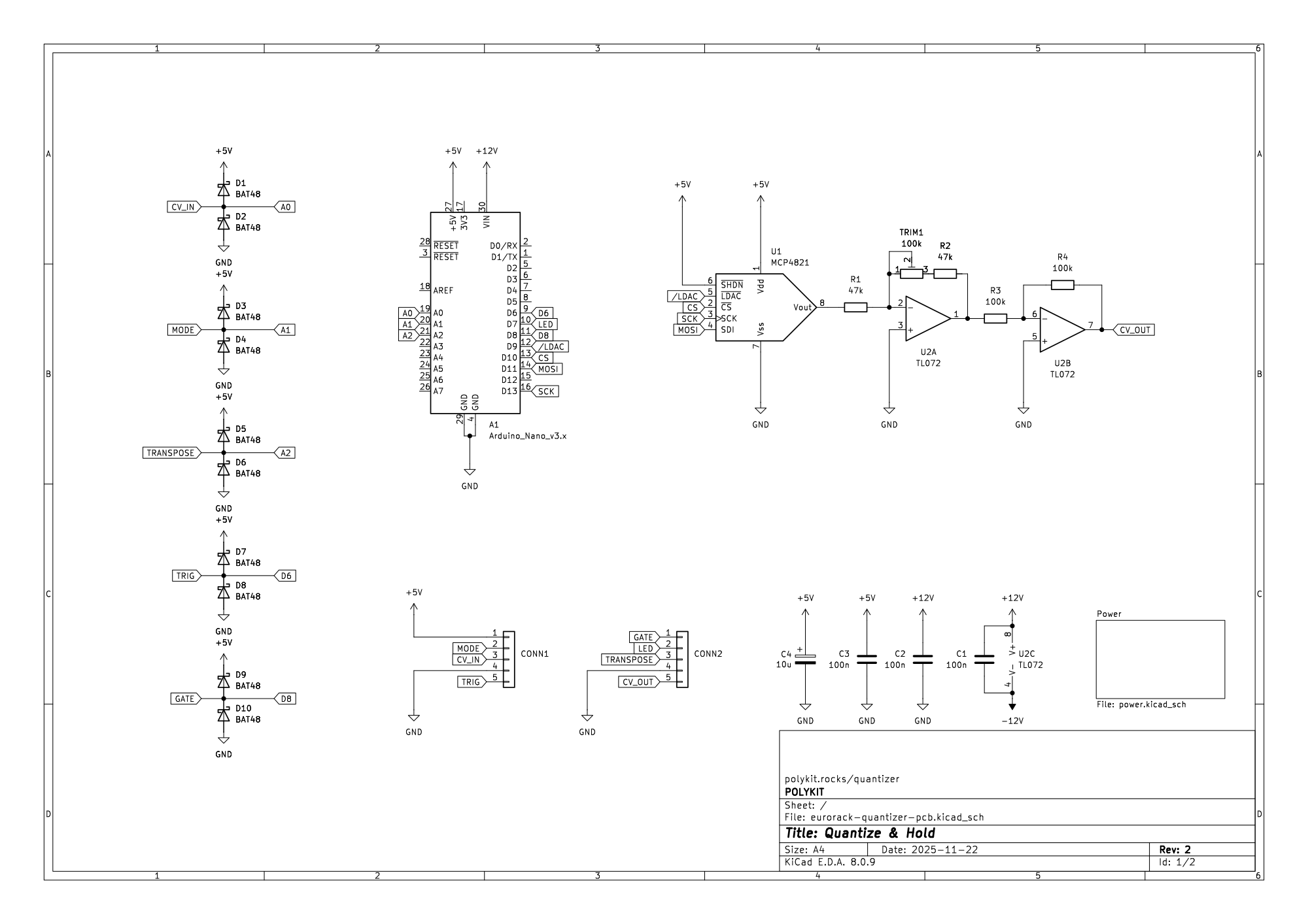
Inside the module, an Arduino continuously reads the input control voltage using its built-in analog-to-digital converter (ADC). Each reading is converted into a semitone index and mapped to the nearest valid note according to the selected scale. Scales define which semitone steps (0–11 within an octave) are permitted. Once the closest allowed note is identified, the Arduino computes the corresponding output voltage and sends it to a 12-bit DAC to generate a stable pitch CV.
In continuous mode, the module performs this process on every ADC update and refreshes the output whenever the input voltage changes. The Gate output pulses whenever the quantized pitch shifts to a new note.
In hold behavior, the Trigger input determines whether a change at the CV input is allowed to update the output. On every detected voltage change, the firmware checks the Trigger level:
- If the Trigger input is high, the new value is sampled, quantized, and sent to the output.
- If the Trigger input is low, the change is ignored and the previous output voltage is held.
This effectively turns the module into a sample-and-hold style quantizer when the Trigger line is driven by an external gate or clock.
The module distinguishes between “continuous” and “hold” operation automatically. If no cable is inserted into the Trigger jack, the input is normalled to 5V (logic high), so every voltage change is accepted and the output updates continuously. When a cable is connected, the external signal on the Trigger jack controls when updates are allowed.
The Scale Mode control (and its optional CV input) selects one of the predefined scales. The Transpose control shifts the quantized note up or down by up to two octaves. Both controls are applied after quantization to maintain correct musical intervals.
The quantized value is converted into a control voltage using an external 12-bit DAC (MCP4821). The DAC provides a full-scale output of 4.096V, which is routed into an analog output stage based on a rail-to-rail op-amp configured for a nominal gain of 2. This produces a theoretical maximum output of approximately 8.192V for 1V/oct systems. The TRIM1 trimmer adjusts the op-amp gain so the stage achieves an accurate 2× amplification, ensuring 1V/oct scaling across the full output range.
Supported Scales#
The module supports the following scales by default:
- Chromatic
- Major
- Natural Minor
- Pentatonic Major
- Pentatonic Minor
- Dorian
- Mixolydian
- Whole Tone
- Harmonic Minor
- Pass-through (unquantized)
Scales that consist out of full semitones can be easily added by adjusting the SCALES array in the source code.
Build Guide#
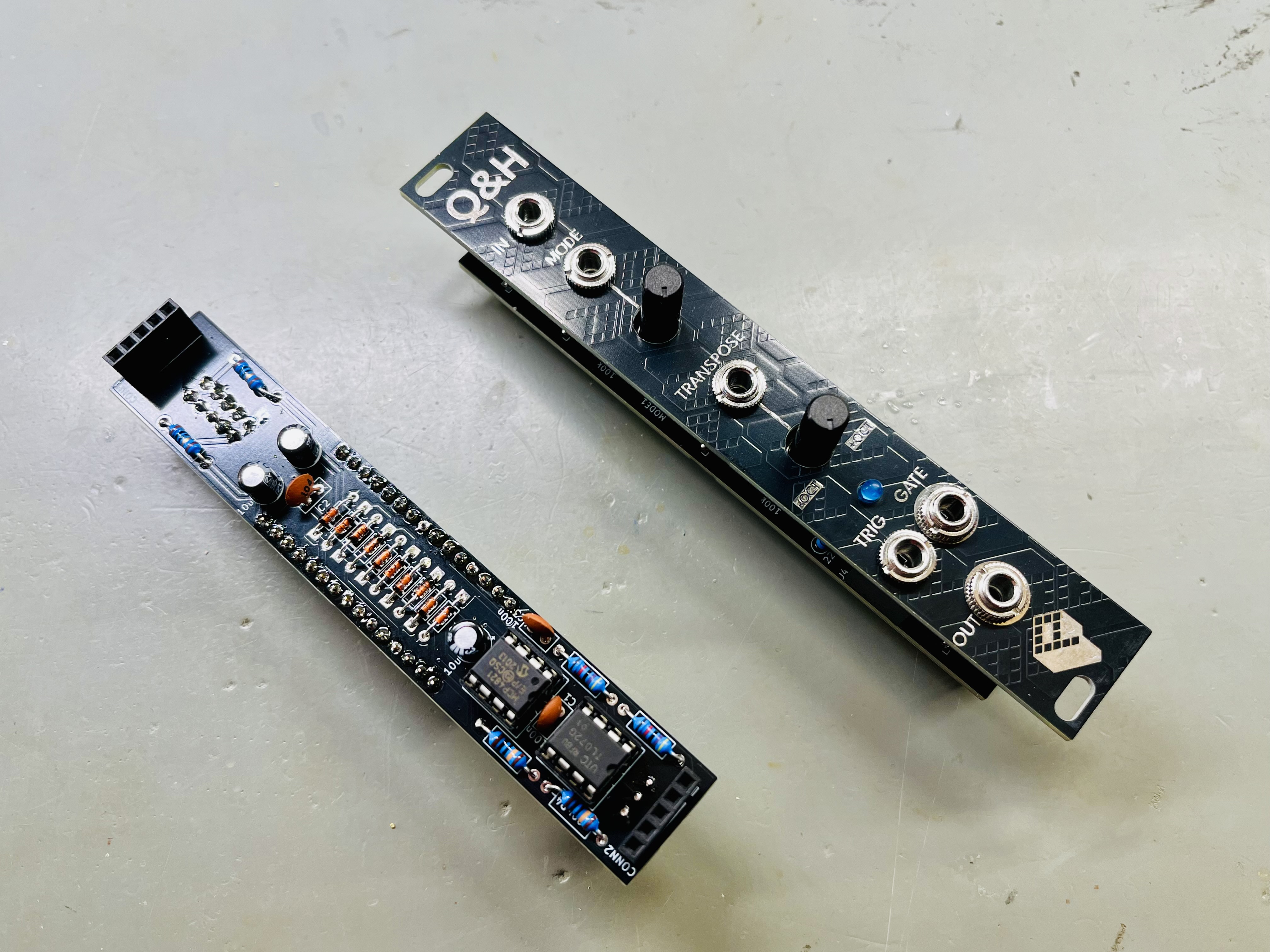
The build is straightforward and well-suited for anyone with basic soldering experience. The module uses only through-hole components, making assembly simple and accessible. The design consists of three PCBs: the front panel, a control/jack board, and the main circuit board.
Start by populating the main circuit board. Begin with the lowest-profile components (resistors, diodes, small capacitors) and work your way up to taller parts like electrolytic capacitors and IC sockets. Leave the LEDs, jacks, and potentiometers on the control board for last.
When mounting the LEDs, jacks and potentiometer, first place them on the board, then align and secure the front panel before soldering. This ensures proper mechanical alignment and a clean fit.
Once all components are soldered, insert the ICs into their sockets — pay close attention to orientation and match the notch on the IC to the marking on the silkscreen.
With the boards fully populated, stack them together using the pin header and socket connections labelled CONN1/CONN1 and CONN2/CONN2. Ensure that all pins are properly aligned before pressing the boards together to avoid bent pins or poor connections.
Each component location is clearly labelled with its designator and value on the PCB silkscreen. Refer to the BOM below for additional details on component types and values.
See the Component Basics guide for help identifying parts.
First Power-On Check#
Before powering the module for the first time, carefully inspect all components, solder joints, and IC orientations.
Check for potential short circuits using a multimeter between -12V, +12V, and ground. For the initial test, it’s best to connect the module to the power supply alone and verify proper operation.
Tuning#
Apply a stable, precise voltage of 2.50V to the input (or any voltage that is a multiple of 1/12V). Turn the Scale Mode knob fully counter-clockwise and set the Transpose control to its center position. Then adjust the TRIM1 precision trimpot until the module’s output matches the input voltage exactly.
Software#
The quantizer runs on open-source Arduino firmware, available on GitHub. You’re free to modify, extend, or completely rebuild the code to suit your own ideas.
To upload or modify the firmware, you’ll need the Arduino IDE (or any compatible toolchain) to compile and flash the code to the microcontroller.
Each kit comes with an Arduino Nano pre-flashed with the standard firmware, so you can get started right away — no programming required unless you want to customize it.
BOM#
Link to interactive BOM of the component board
| Reference | Value | Footprint | Qty | Description |
|---|---|---|---|---|
| A1 | Arduino_Nano_v3.x | Module:Arduino_Nano | 1 | Arduino Nano v3.x |
| C1,C2,C3 | 100n | Capacitor_THT:C_Disc_D5.0mm_W2.5mm_P2.50mm | 3 | Ceramic |
| C4,C5,C6 | 10u | Capacitor_THT:CP_Radial_D5.0mm_P2.50mm | 3 | Electrolytic |
| CONN1, CONN2 | Conn_01x05 | Connector_PinSocket_2.54mm:PinSocket_1x05_P2.54mm_Vertical | 2 | 5-pin socket, 2.54mm |
| D1, D2, D3, D4, D5, D6, D7, D8, D9, D10 | BAT48 | Diode_THT:D_DO-35_SOD27_P7.62mm_Horizontal | 10 | Schottky diode, DO-35 |
| POWER1 | Conn_02x05_Odd_Even | Connector_IDC:IDC-Header_2x05_P2.54mm_Vertical | 1 | IDC 10-pin power connector |
| R1,R2 | 47k | Resistor_THT:R_Axial_DIN0207_L6.3mm_D2.5mm_P10.16mm_Horizontal | 2 | 1/4W 1% resistor |
| R3,R4 | 100k | Resistor_THT:R_Axial_DIN0207_L6.3mm_D2.5mm_P10.16mm_Horizontal | 2 | 1/4W 1% resistor |
| R6,R7 | 10 | Resistor_THT:R_Axial_DIN0207_L6.3mm_D2.5mm_P10.16mm_Horizontal | 2 | 1/4W 1% resistor |
| TRIM1 | 100k | Potentiometer_THT:Potentiometer_Bourns_3296W_Vertical | 1 | Trim-potentiometer |
| U1 | MCP4821 | Package_DIP:DIP-8_W7.62mm_Socket_LongPads | 1 | 12-bit DAC, SPI, DIP-8 |
| U2 | TL072 | Package_DIP:DIP-8_W7.62mm_Socket_LongPads | 1 | Dual op-amp, DIP-8 |
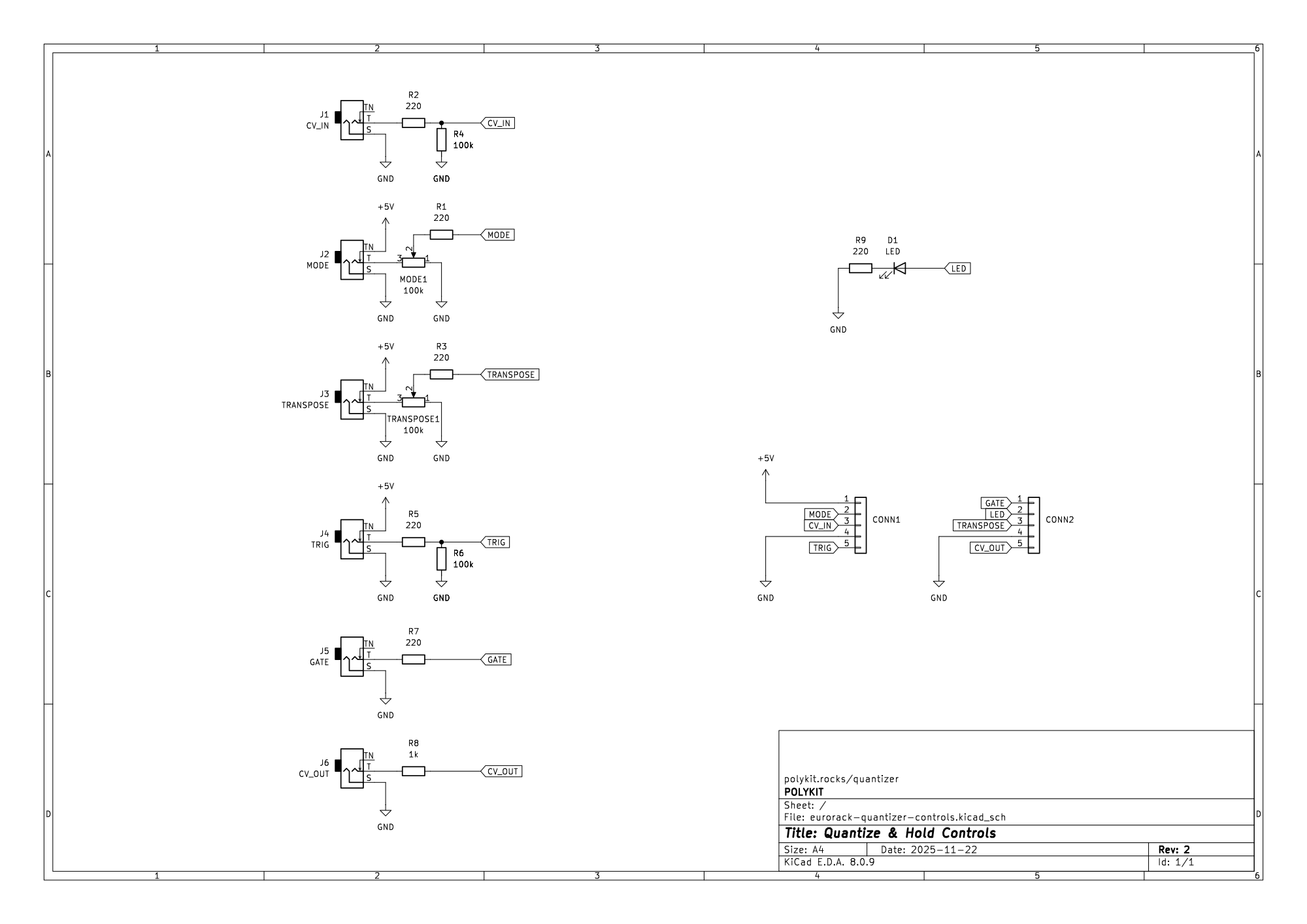
Link to interactive BOM of the control board
| Reference | Value | Footprint | Qty | Description |
|---|---|---|---|---|
| CONN1, CONN2 | Conn_01x05 | Connector_PinHeader_2.54mm:PinHeader_1x05_P2.54mm_Vertical | 2 | 5-pin header, 2.54mm |
| D1 | LED | LED_THT:LED_D3.0mm | 1 | LED, 3mm |
| J1 | CV_IN | Connector_Audio:Jack_3.5mm_QingPu_WQP-PJ398SM_Vertical_CircularHoles | 1 | Mono Thonkiconn 3.5mm jack sockets |
| J2 | MODE | Connector_Audio:Jack_3.5mm_QingPu_WQP-PJ398SM_Vertical_CircularHoles | 1 | Mono Thonkiconn 3.5mm jack sockets |
| J3 | TRANSPOSE | Connector_Audio:Jack_3.5mm_QingPu_WQP-PJ398SM_Vertical_CircularHoles | 1 | Mono Thonkiconn 3.5mm jack sockets |
| J4 | TRIG | Connector_Audio:Jack_3.5mm_QingPu_WQP-PJ398SM_Vertical_CircularHoles | 1 | Mono Thonkiconn 3.5mm jack sockets |
| J5 | GATE | Connector_Audio:Jack_3.5mm_QingPu_WQP-PJ398SM_Vertical_CircularHoles | 1 | Mono Thonkiconn 3.5mm jack sockets |
| J6 | CV_OUT | Connector_Audio:Jack_3.5mm_QingPu_WQP-PJ398SM_Vertical_CircularHoles | 1 | Mono Thonkiconn 3.5mm jack sockets |
| MODE1, TRANSPOSE1 | 100k | Potentiometer_THT:Potentiometer_Alps_RK09K_Single_Vertical | 2 | Linear, mono, vertical, threaded or non-threaded |
| R1,R2,R3,R5 | 220 | Resistor_THT:R_Axial_DIN0207_L6.3mm_D2.5mm_P10.16mm_Horizontal | 4 | 1/4W 1% resistor |
| R4,R6 | 100k | Resistor_THT:R_Axial_DIN0207_L6.3mm_D2.5mm_P10.16mm_Horizontal | 2 | 1/4W 1% resistor |
| R7,R9 | 220 | Resistor_THT:R_Axial_DIN0207_L6.3mm_D2.5mm_P2.54mm_Vertical | 2 | 1/4W 1% resistor |
| R8 | 1k | Resistor_THT:R_Axial_DIN0207_L6.3mm_D2.5mm_P10.16mm_Horizontal | 1 | 1/4W 1% resistor |
Schematics#