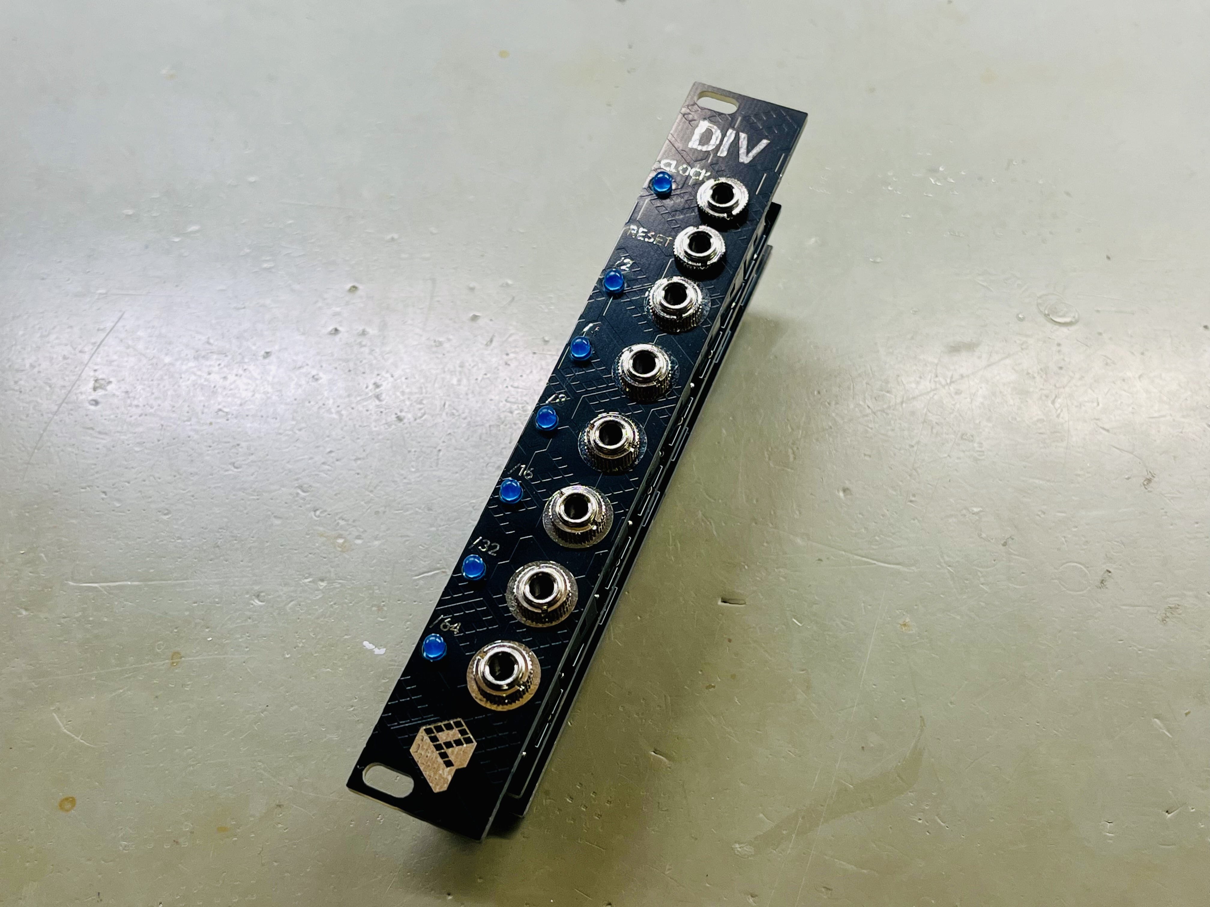
This clock divider is built around the CD4024 CMOS 7-stage binary counter. It divides an incoming clock signal by powers of two, providing six simultaneous outputs. It’s a compact and reliable utility module that works well alongside sequencers, drum triggers, or other clock-driven circuits.
Perfect companion for the Sequencer.
Buy kit or PCBs in my storeKey Specs#
- Clock divider based on CD4024 binary counter
- Clock input
- Reset input
- 6 outputs (/2 to /64)
- 4HP panel width
Circuit Description#
The core of the circuit is a CD4024 binary counter acting as a clock divider. The input clock passes through an NPN transistor (Q1) which inverts the signal — the 4024 expects a low-going clock transition for counting.

A capacitor (C3) converts rising voltages into clean, short pulses to drive the reset. The reset circuit uses two NPN transistors (Q2 and Q3) configured as a Schmitt-trigger, ensuring correct voltage levels to reliably reset the counter to zero. Capacitor C7 provides an automatic power-on reset, initializing the counter to a known state every time the module is powered. Diodes D1 and D2 protect the transistor bases from negative input voltages.
Each of the six counter outputs is buffered through an op-amp stage. This allows the module to drive LEDs for visual feedback and ensures voltage levels on the outputs for interfacing with other modules.
Build Guide#
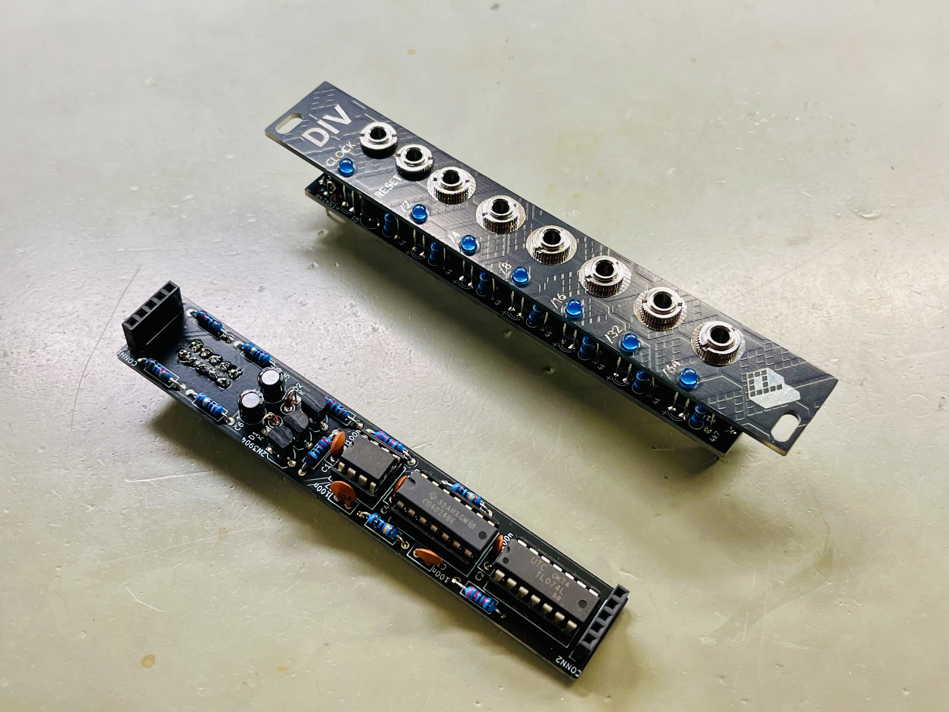
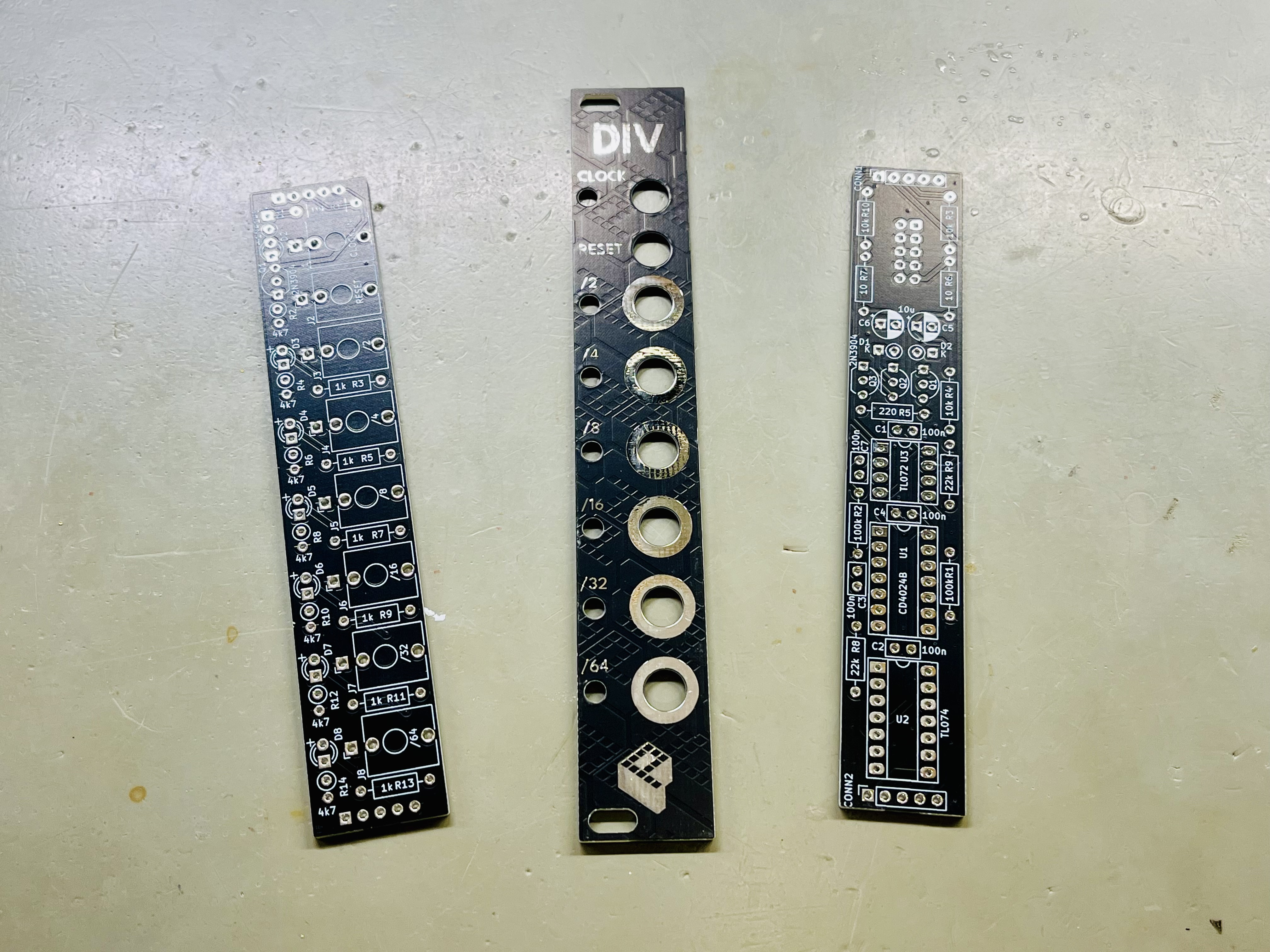
The build is straightforward and well-suited for anyone with basic soldering experience. The module uses only through-hole components, making assembly simple and accessible. The design consists of three PCBs: the front panel, a control/jack board, and the main circuit board.
Start by populating the main circuit board. Begin with the lowest-profile components (resistors, diodes, small capacitors) and work your way up to taller parts like electrolytic capacitors and IC sockets. Leave the LEDs, jacks, and potentiometers for last.
When mounting the LEDs, jacks and potentiometer, first place them on the board, then align and secure the front panel before soldering. This ensures proper mechanical alignment and a clean fit.
Once all components are soldered, insert the ICs into their sockets — pay close attention to orientation and match the notch on the IC to the marking on the silkscreen.
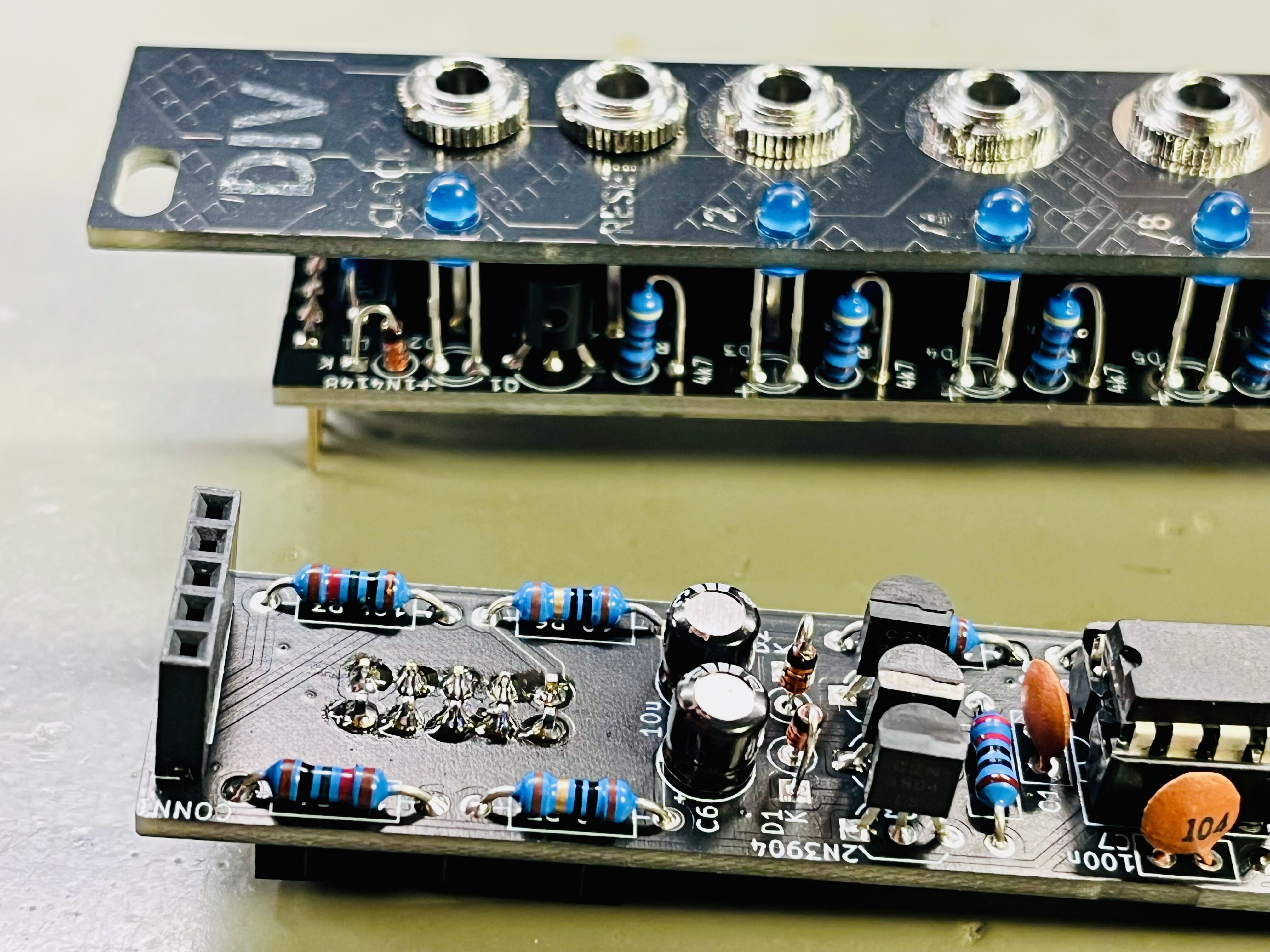
With the boards fully populated, stack them together using the pin header and socket connections labelled CONN1/CONN1 and CONN2/CONN2. Ensure that all pins are properly aligned before pressing the boards together to avoid bent pins or poor connections.
Each component location is clearly labelled with its designator and value on the PCB silkscreen. Refer to the BOM below for additional details on component types and values.
See the Component Basics guide for help identifying parts.
First Power-On Check#
Before powering the module for the first time, carefully inspect all components, solder joints, and IC orientations.
Check for potential short circuits using a multimeter between -12 V / +12 V and ground. For the initial test, it’s best to connect the module to the power supply alone and verify proper operation.
BOM#
Link to interactive BOM of the component board
| Reference | Value | Footprint | Qty | Description |
|---|---|---|---|---|
| C1,C2,C3,C4,C7 | 100n | Capacitor_THT:C_Disc_D5.0mm_W2.5mm_P2.50mm | 5 | Ceramic |
| C5,C6 | 10u | Capacitor_THT:CP_Radial_D5.0mm_P2.50mm | 2 | Electrolytic |
| CONN1,CONN2 | Conn_01x05 | Connector_PinSocket_2.54mm:PinSocket_1x05_P2.54mm_Vertical | 2 | 5-pin pin sockets, 2.54mm |
| D1,D2 | 1N4148 | Diode_THT:D_DO-35_SOD27_P2.54mm_Vertical_KathodeUp | 2 | Switching diode, DO-35 |
| POWER1 | Conn_02x05_Odd_Even | Connector_IDC:IDC-Header_2x05_P2.54mm_Vertical | 1 | IDC 10-pin power connector |
| Q1,Q2,Q3 | 2N3904 | Package_TO_SOT_THT:TO-92_Inline_Wide | 3 | NPN Transistor, TO-92 |
| R1,R2 | 100k | Resistor_THT:R_Axial_DIN0207_L6.3mm_D2.5mm_P10.16mm_Horizontal | 2 | 1/4W 1% resistor |
| R3,R4,R10 | 10k | Resistor_THT:R_Axial_DIN0207_L6.3mm_D2.5mm_P10.16mm_Horizontal | 3 | 1/4W 1% resistor |
| R5 | 220 | Resistor_THT:R_Axial_DIN0207_L6.3mm_D2.5mm_P10.16mm_Horizontal | 1 | 1/4W 1% resistor |
| R6,R7 | 10 | Resistor_THT:R_Axial_DIN0207_L6.3mm_D2.5mm_P10.16mm_Horizontal | 2 | 1/4W 1% resistor |
| R8,R9 | 22k | Resistor_THT:R_Axial_DIN0207_L6.3mm_D2.5mm_P10.16mm_Horizontal | 2 | 1/4W 1% resistor |
| U1 | CD4024B | Package_DIP:DIP-14_W7.62mm_Socket_LongPads | 1 | 7-stage binary counter IC |
| U2 | TL074 | Package_DIP:DIP-14_W7.62mm_Socket_LongPads | 1 | Quad Operational Amplifiers, DIP-14 |
| U3 | TL072 | Package_DIP:DIP-8_W7.62mm_Socket_LongPads | 1 | Dual Operational Amplifiers, DIP-8 |
Link to interactive BOM of the control board
| Reference | Value | Footprint | Qty | Description |
|---|---|---|---|---|
| CONN1,CONN2 | Conn_01x05 | Connector_PinHeader_2.54mm:PinHeader_1x05_P2.54mm_Vertical | 2 | 5-pin header, 2.54mm |
| D1 | 1N4148 | Diode_THT:D_DO-35_SOD27_P2.54mm_Vertical_KathodeUp | 1 | Switching diode, DO-35 |
| D2,D3,D4,D5,D6,D7,D8 | LED | LED_THT:LED_D3.0mm | 7 | LED, 3mm |
| J1 | CLOCK_IN | Connector_Audio:Jack_3.5mm_QingPu_WQP-PJ398SM_Vertical_CircularHoles | 1 | Mono Thonkiconn 3.5mm jack sockets |
| J2 | RESET | Connector_Audio:Jack_3.5mm_QingPu_WQP-PJ398SM_Vertical_CircularHoles | 1 | Mono Thonkiconn 3.5mm jack sockets |
| J3 | /2 | Connector_Audio:Jack_3.5mm_QingPu_WQP-PJ398SM_Vertical_CircularHoles | 1 | Mono Thonkiconn 3.5mm jack sockets |
| J4 | /4 | Connector_Audio:Jack_3.5mm_QingPu_WQP-PJ398SM_Vertical_CircularHoles | 1 | Mono Thonkiconn 3.5mm jack sockets |
| J5 | /8 | Connector_Audio:Jack_3.5mm_QingPu_WQP-PJ398SM_Vertical_CircularHoles | 1 | Mono Thonkiconn 3.5mm jack sockets |
| J6 | /16 | Connector_Audio:Jack_3.5mm_QingPu_WQP-PJ398SM_Vertical_CircularHoles | 1 | Mono Thonkiconn 3.5mm jack sockets |
| J7 | /32 | Connector_Audio:Jack_3.5mm_QingPu_WQP-PJ398SM_Vertical_CircularHoles | 1 | Mono Thonkiconn 3.5mm jack sockets |
| J8 | /64 | Connector_Audio:Jack_3.5mm_QingPu_WQP-PJ398SM_Vertical_CircularHoles | 1 | Mono Thonkiconn 3.5mm jack sockets |
| Q1 | 2N3904 | Package_TO_SOT_THT:TO-92_Inline_Wide | 1 | NPN Transistor, TO-92 |
| R1 | 10k | Resistor_THT:R_Axial_DIN0207_L6.3mm_D2.5mm_P10.16mm_Horizontal | 1 | 1/4W 1% resistor |
| R2,R4,R6,R8,R10,R12,R14 | 4k7 | Resistor_THT:R_Axial_DIN0207_L6.3mm_D2.5mm_P2.54mm_Vertical | 7 | 1/4W 1% resistor |
| R3,R5,R7,R9,R11,R13 | 1k | Resistor_THT:R_Axial_DIN0207_L6.3mm_D2.5mm_P10.16mm_Horizontal | 6 | 1/4W 1% resistor |
Schematics#


Changelog#
- rev3: add counter reset when powered
- rev2: add Schmitt-trigger on reset input, make it work with low voltages
References#
https://www.midcentury-modular.com/blog/cmos-clock-dividers