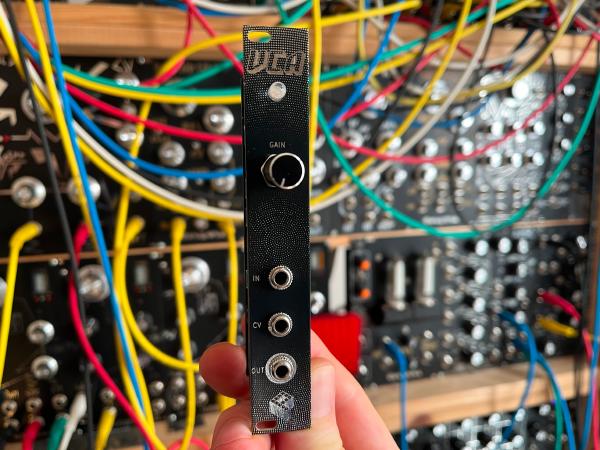
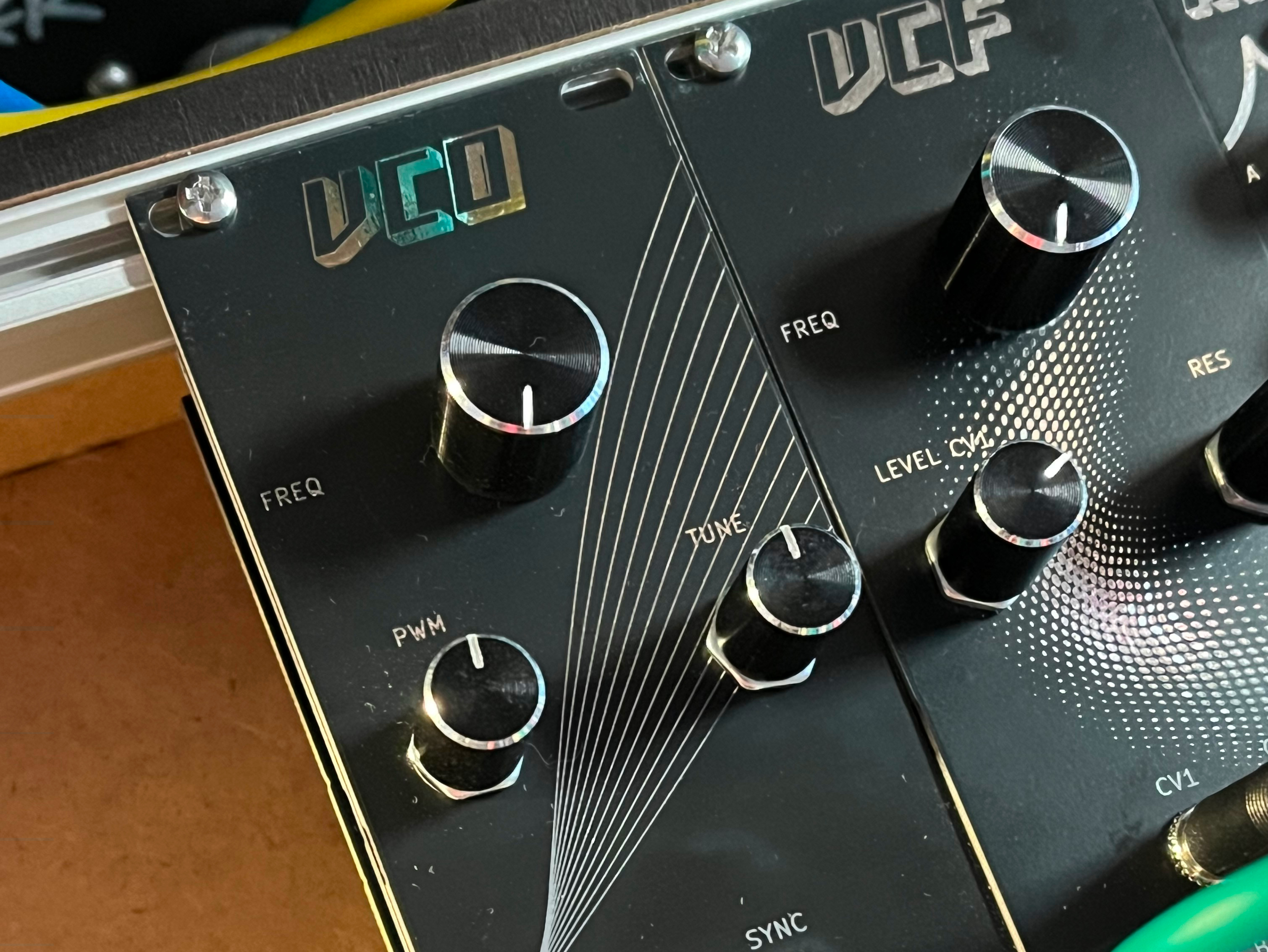
This voltage controlled oscillator is part of my Eurorack series. It outputs a saw and square signal, and its frequency is controlled by a 1V/Octave control voltage. There are CV inputs for frequency modulation, pulse width and oscillator sync. In addition, there are controls for frequency, fine tuning and pulse width.
Buy kit or PCBs in my storeKey features#
- voltage-controlled oscillator
- saw and square output
- kit/PCB with pre-soldered SMD dual-transistor
- 1V/Octave frequency CV input
- CV for FM, PWM and oscillator sync
- frequency, fine-tune and PWM controls
- easy to build, all through-hole components
- 10 HP

Videos#
How it works#
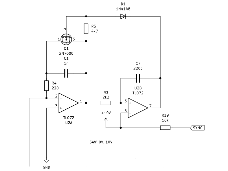
It’s a classic design with an oscillator core made out of a capacitor and a comparator. The capacitor C1 is charged, and when it reaches a threshold voltage of 10V it is shorted through the MOSFET transistor Q1 and the cycle starts again. The frequency is controlled by an exponential current sink that is formed by the dual-transistor Q2. It takes current out of the oscillator core and changes the time for the capacitor to charge and, subsequently, its frequency. It needs to be exponential to double (or half) the frequency every octave.
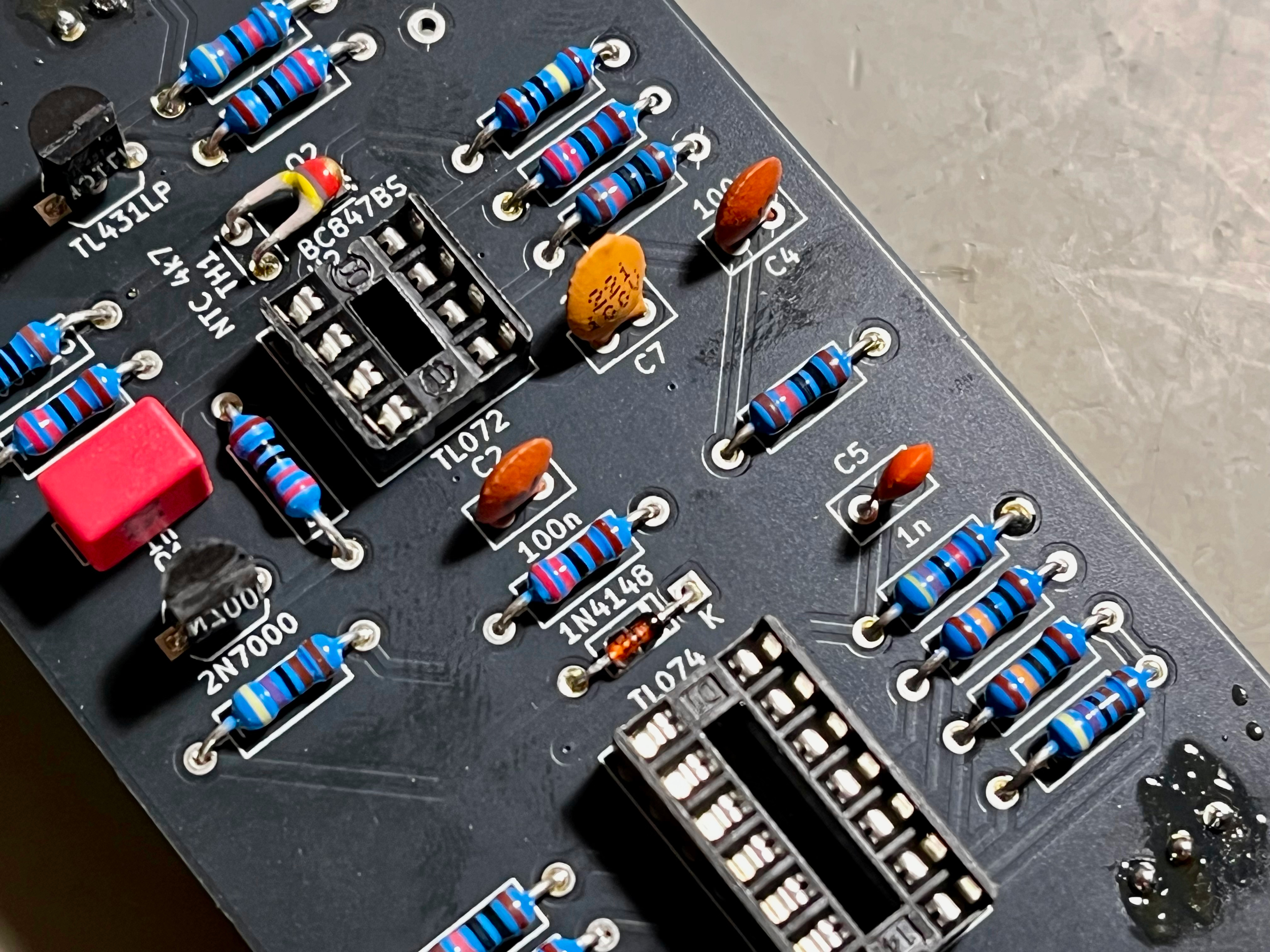
Almost perfectly matched transistors in the current sink are crucial for good frequency tracking over multiple octaves. I decided to use a dual-transistor SMD package that is pre-assembled on the kits and PCBs in my store. It delivers good tracking over 5-6 octaves for a fair price. The NTC thermistor TH1 is used for compensation of temperature changes.
There is a TL431 shunt regulator to provide a precise reference voltage of +5V.
The PWM input and control pot change the pulse width of the square signal and is at 0% on both ends.
The SYNC input allows a sort of soft-syncing to the frequency of another oscillator. All sorts of weird effects and creating overtones is possible with this input.
Assembly#
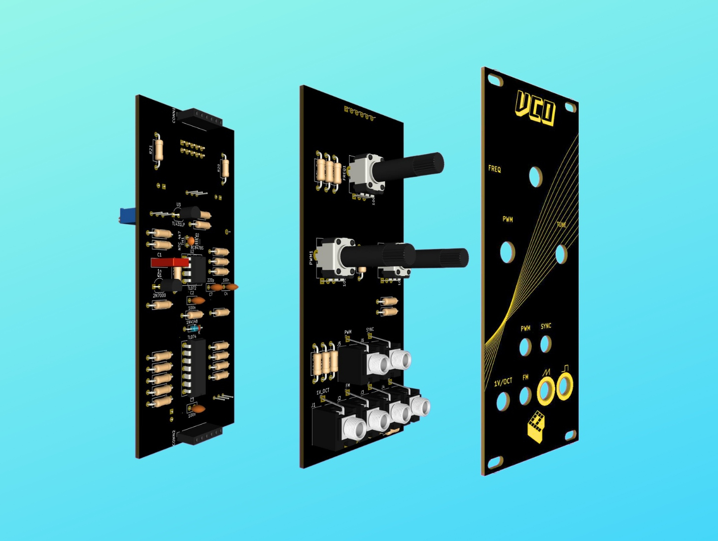
The build is pretty straight forward. The module only consists of through-hole components and is easy to assemble. There are three boards: a front panel, a board for controls/jacks, and a board for the circuit.
First, solder all parts on the component board. Keep the jacks and potentiometers for the end. Begin with the components with the lowest profile and work your way up. Screw the jacks and potentiometer to the front panel before soldering them. All components have a fixed designator and a component value printed on the board. Additional information on the parts can be found in the BOM below.
See the Component Basics guide for help identifying parts.
Tuning#
Connect the VCO to power and let it warm up for 15 minutes before starting the tuning process. Ideally, use the power supply that you are going to use later on.
Reference voltage#
A multimeter is needed for this. Adjust the precision trim potentiometer TRIM_REF1 until you measure +5.00V between test point REF1 and ground.
Frequency tuning#
I used a tuning device for this, but a tuning app for your mobile will also work just fine. This is how to tune the oscillator:
- Turn the frequency knob fully counter-clockwise and the fine-tune/PWM controls to a centre position.
- Tune the oscillator roughly to a base note, e.g. C4. Do this by applying the correct CV to the 1V/Oct input and adjusting the offset trim pot
TRIM_OFFSET1. - Next is to get the right scale, which is the distance between the notes. Adjust scale
TRIM_SCALE1until you have the correct interval between two notes, e.g. your base note C4 and D4. While changing scale, overall tuning will change, so go back to your base note from time to time by adjusting the offset. When you are quite close to the correct scale, fine-tune it for a whole octave, e.g. using notes C4 and C5.
BOM#
Link to interactive BOM of the component board
| Reference | Value | Footprint | Qty | Description |
|---|---|---|---|---|
| C1 | 1n | Capacitor_THT:C_Rect_L7.2mm_W2.5mm_P5.00mm_FKS2_FKP2_MKS2_MKP2 | 1 | Film |
| C2,C3,C4 | 100n | Capacitor_THT:C_Disc_D5.0mm_W2.5mm_P2.50mm | 3 | Ceramic |
| C5 | 1n | Capacitor_THT:C_Disc_D5.0mm_W2.5mm_P2.50mm | 1 | Ceramic |
| C6,C8,C9 | 10u | Capacitor_THT:CP_Radial_D5.0mm_P2.50mm | 3 | Electrolytic |
| C7 | 220p | Capacitor_THT:C_Disc_D5.0mm_W2.5mm_P2.50mm | 1 | Ceramic |
| CONN1,CONN2 | Conn_01x06 | Connector_PinSocket_2.54mm:PinSocket_1x06_P2.54mm_Vertical | 2 | 6-pin socket |
| D1 | 1N4148 | Diode_THT:D_DO-35_SOD27_P7.62mm_Horizontal | 1 | |
| POWER1 | Conn_02x05_Odd_Even | Connector_IDC:IDC-Header_2x05_P2.54mm_Vertical | 1 | IDC 10-pin |
| Q1 | 2N7000 | Package_TO_SOT_THT:TO-92_Inline_Wide | 1 | N-channel MOSFET |
| Q2 | BC847BS | Package_TO_SOT_SMD:SOT-363_SC-70-6 | 1 | Dual transistor, SMD |
| R1,R8 | 47k | Resistor_THT:R_Axial_DIN0207_L6.3mm_D2.5mm_P10.16mm_Horizontal | 2 | 1/4W 1% resistor |
| R2,R4 | 220 | Resistor_THT:R_Axial_DIN0207_L6.3mm_D2.5mm_P10.16mm_Horizontal | 2 | 1/4W 1% resistor |
| R3,R6,R11 | 2k2 | Resistor_THT:R_Axial_DIN0207_L6.3mm_D2.5mm_P10.16mm_Horizontal | 3 | 1/4W 1% resistor |
| R5,R10,R18 | 4k7 | Resistor_THT:R_Axial_DIN0207_L6.3mm_D2.5mm_P10.16mm_Horizontal | 3 | 1/4W 1% resistor |
| R7,R15,R17,R19 | 10k | Resistor_THT:R_Axial_DIN0207_L6.3mm_D2.5mm_P10.16mm_Horizontal | 4 | 1/4W 1% resistor |
| R9 | 1M | Resistor_THT:R_Axial_DIN0207_L6.3mm_D2.5mm_P10.16mm_Horizontal | 1 | 1/4W 1% resistor |
| R12,R14,R22 | 100k | Resistor_THT:R_Axial_DIN0207_L6.3mm_D2.5mm_P10.16mm_Horizontal | 3 | 1/4W 1% resistor |
| R13 | 100 | Resistor_THT:R_Axial_DIN0207_L6.3mm_D2.5mm_P10.16mm_Horizontal | 1 | 1/4W 1% resistor |
| R16 | 470k | Resistor_THT:R_Axial_DIN0207_L6.3mm_D2.5mm_P10.16mm_Horizontal | 1 | 1/4W 1% resistor |
| R20,R21 | 10 | Resistor_THT:R_Axial_DIN0207_L6.3mm_D2.5mm_P10.16mm_Horizontal | 2 | 1/4W 1% resistor |
| TH1 | NTC 4k7 | Capacitor_THT:C_Disc_D3.0mm_W2.0mm_P2.50mm | 1 | Temperature dependent resistor, negative temperature coefficient |
| TRIM_OFFSET1,TRIM_REF1 | 100k | Potentiometer_THT:Potentiometer_Bourns_3296W_Vertical | 2 | Trim-potentiometer |
| TRIM_SCALE1 | 100 | Potentiometer_THT:Potentiometer_Bourns_3296W_Vertical | 1 | Trim-potentiometer |
| U1 | TL074 | Package_DIP:DIP-14_W7.62mm_Socket_LongPads | 1 | Quad op-amp |
| U2 | TL072 | Package_DIP:DIP-8_W7.62mm_Socket_LongPads | 1 | Dual op-amp |
| U3 | TL431LP | Package_TO_SOT_THT:TO-92_Inline_Wide | 1 | Shunt regulator for reference voltage |
Link to interactive BOM of the control board
| Reference | Value | Footprint | Qty | Description |
|---|---|---|---|---|
| CONN1,CONN2 | Conn_01x06 | Connector_PinHeader_2.54mm:PinHeader_1x06_P2.54mm_Vertical | 2 | 6-pin header |
| FREQ1,PWM1,TUNE1 | 100k | Potentiometer_THT:Potentiometer_Alpha_RD901F-40-00D_Single_Vertical | 3 | linear, vertical, threaded, 6mm |
| J1 | 1V_OCT | Connector_Audio:Jack_3.5mm_QingPu_WQP-PJ398SM_Vertical_CircularHoles | 1 | Thonkiconn 3.5mm jack sockets |
| J2 | FM | Connector_Audio:Jack_3.5mm_QingPu_WQP-PJ398SM_Vertical_CircularHoles | 1 | Thonkiconn 3.5mm jack sockets |
| J3 | OUT_RAMP | Connector_Audio:Jack_3.5mm_QingPu_WQP-PJ398SM_Vertical_CircularHoles | 1 | Thonkiconn 3.5mm jack sockets |
| J4 | OUT_PULSE | Connector_Audio:Jack_3.5mm_QingPu_WQP-PJ398SM_Vertical_CircularHoles | 1 | Thonkiconn 3.5mm jack sockets |
| J5 | PWM | Connector_Audio:Jack_3.5mm_QingPu_WQP-PJ398SM_Vertical_CircularHoles | 1 | Thonkiconn 3.5mm jack sockets |
| J6 | SYNC | Connector_Audio:Jack_3.5mm_QingPu_WQP-PJ398SM_Vertical_CircularHoles | 1 | Thonkiconn 3.5mm jack sockets |
| R1 | 22k | Resistor_THT:R_Axial_DIN0207_L6.3mm_D2.5mm_P10.16mm_Horizontal | 1 | 1/4W 1% resistor |
| R2,R5 | 220k | Resistor_THT:R_Axial_DIN0207_L6.3mm_D2.5mm_P10.16mm_Horizontal | 2 | 1/4W 1% resistor |
| R3,R4,R8 | 100k | Resistor_THT:R_Axial_DIN0207_L6.3mm_D2.5mm_P10.16mm_Horizontal | 3 | 1/4W 1% resistor |
| R6,R7 | 1k | Resistor_THT:R_Axial_DIN0207_L6.3mm_D2.5mm_P10.16mm_Horizontal | 2 | 1/4W 1% resistor |
| R9,R10 | 1M | Resistor_THT:R_Axial_DIN0207_L6.3mm_D2.5mm_P10.16mm_Horizontal | 2 | 1/4W 1% resistor |
Schematics#


References#
https://yusynth.net/Modular/index_en.html
https://kassu2000.blogspot.com/2015/12/vco-part-1-core.html
https://modwiggler.com/forum/viewtopic.php?t=92595
http://www.synthdiy.com/files/2008/RolandJupiter8-ServiceNotes.pdf#page=15
https://assets.nexperia.com/documents/data-sheet/BC847BS.pdf