
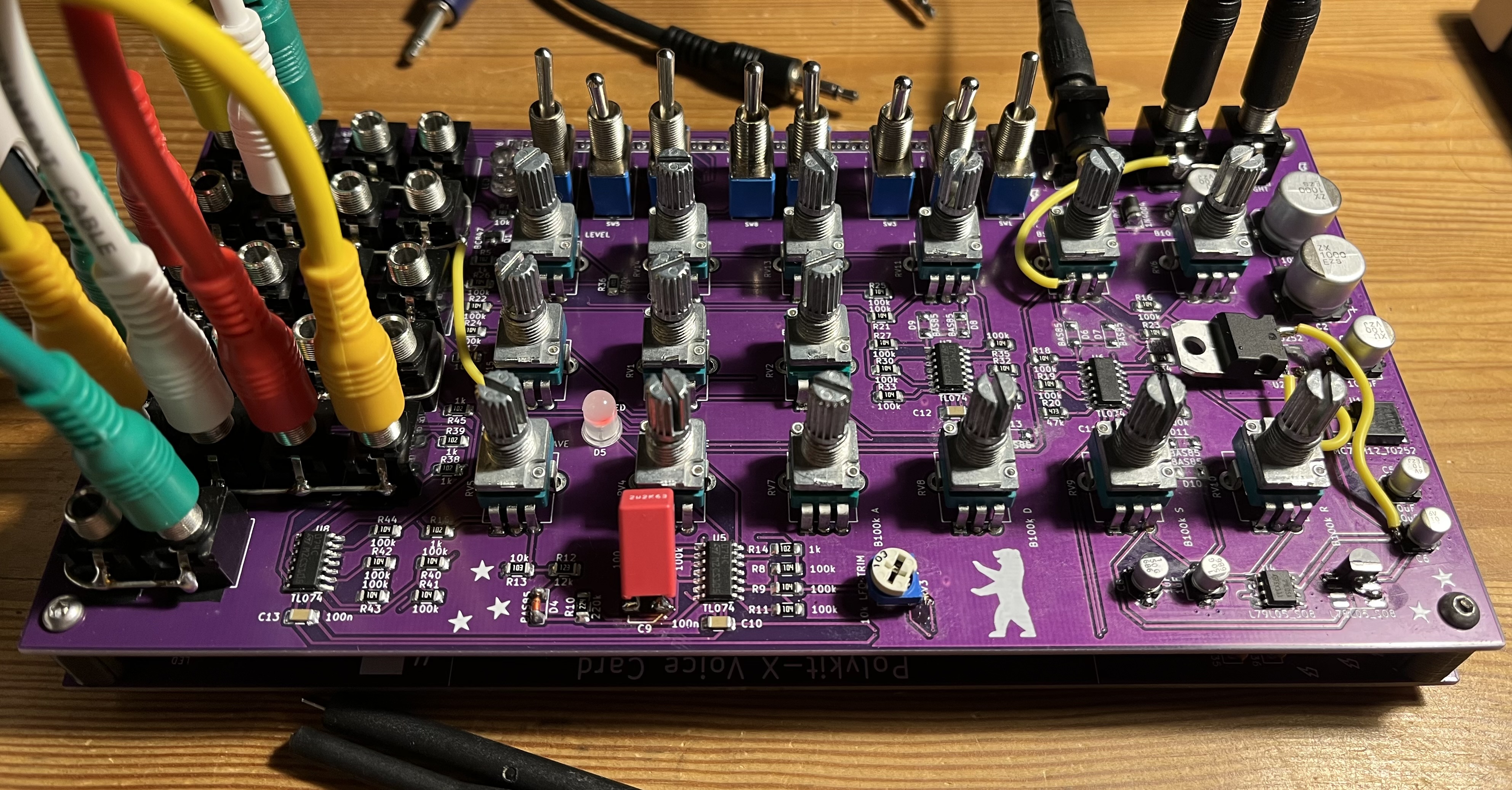
Starting out with building your own synthesizers can be confusing at first. There are many different components, they come in a variety of packages, their identifiers vary, and sourcing the right parts can sometimes feel like a challenge of its own.
This overview should help you identify and understand the most common components you’ll encounter when building synth DIY kits. Once you’ve soldered a few modules, these parts—and their quirks—will quickly start to feel familiar.
Capacitors#
Capacitors store electrical charge. Their capacitance is measured in Farads (F), though in practice you’ll mostly encounter much smaller units such as microfarads (µF), nanofarads (nF), and picofarads (pF).
In my kits I use ceramic, film, and electrolytic capacitors. Most capacitors are marked with:
- a capacitance value
- a voltage rating
- a tolerance (precision)
Always make sure the voltage rating is suitable for your application. For Eurorack modules (±12 V ≙ 24 Vpp), 35 V or higher is a good and safe choice.
In schematics and BOMs (bill of materials), capacitors are designated with a C followed by a number (e.g. C1). On the PCB you’ll usually find a box or outline labeled with both the designator and the required capacitance.
Ceramic Capacitors#
Ceramic capacitors are most often used as bypass or decoupling capacitors. Their job is to filter noise and absorb fast voltage spikes. They act as small local energy reservoirs between Vcc and ground, especially close to integrated circuits such as op-amps or logic ICs.
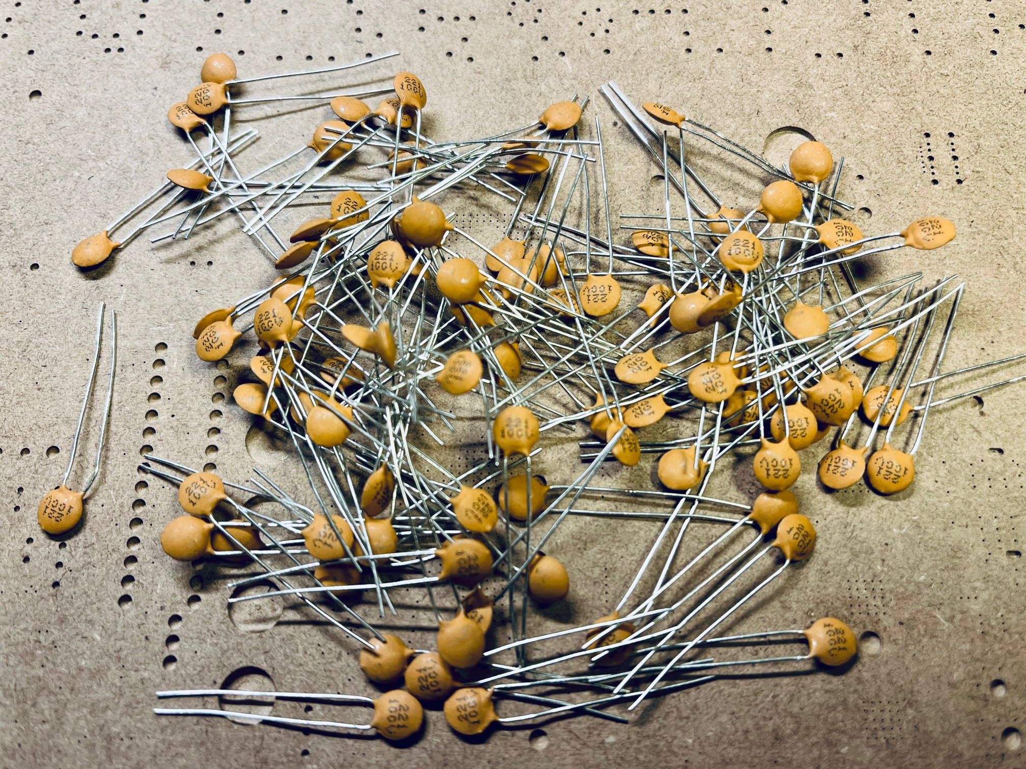
Ceramic capacitors typically use a three-digit code to indicate their value:
5    = 5pF
100  = 10pF × 10⁰ = 10pF
101  = 10pF × 10¹ = 100pF
102  = 10pF × 10² = 1000pF = 1nF
103  = 10pF × 10³ = 10000pF = 10nF
104  = 10pF × 10⁴ = 100000pF = 100nF
200p = 200pF
2p2  = 2.2pF
2n2  = 2.2nF
The first two digits are the value in picofarads, the last digit is the power-of-ten multiplier. Typical tolerances range from 5% to 10%.
Ceramic capacitors are non-polarized (NP), which means orientation does not matter when soldering them into the PCB.
Electrolytic Capacitors#
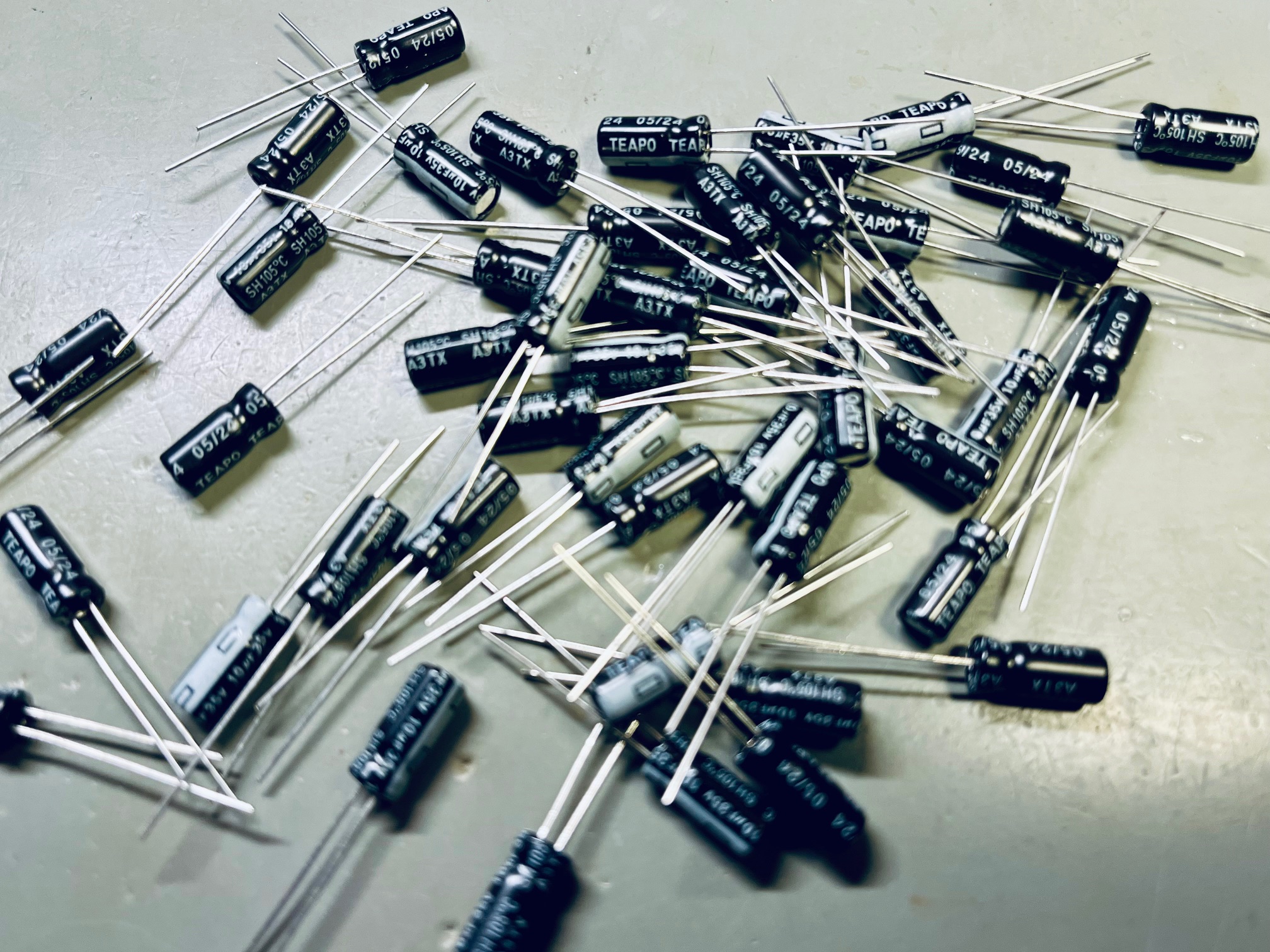
Electrolytic capacitors are used when larger capacitance values are required, usually from around 0.47 µF up to thousands of µF. In synth circuits they are commonly found in:
- power supply filtering
- coupling stages
- envelope and timing circuits
Unlike ceramic capacitors, electrolytics are polarized. This means orientation is critical:
- the negative lead is usually marked with a stripe on the body
- the positive lead is often longer
- PCBs usually indicate polarity with a
+sign or a square pad
Installing an electrolytic capacitor the wrong way around can cause malfunction or even permanent damage.
Electrolytic capacitors are marked with:
- capacitance (usually printed directly, e.g.
10µF) - voltage rating (e.g.
35V)
For Eurorack systems, choose voltage ratings comfortably above the expected voltage. Electrolytics also tend to have wider tolerances (often ±20%), which is normal and usually not a problem in audio circuits.
Film Capacitors#
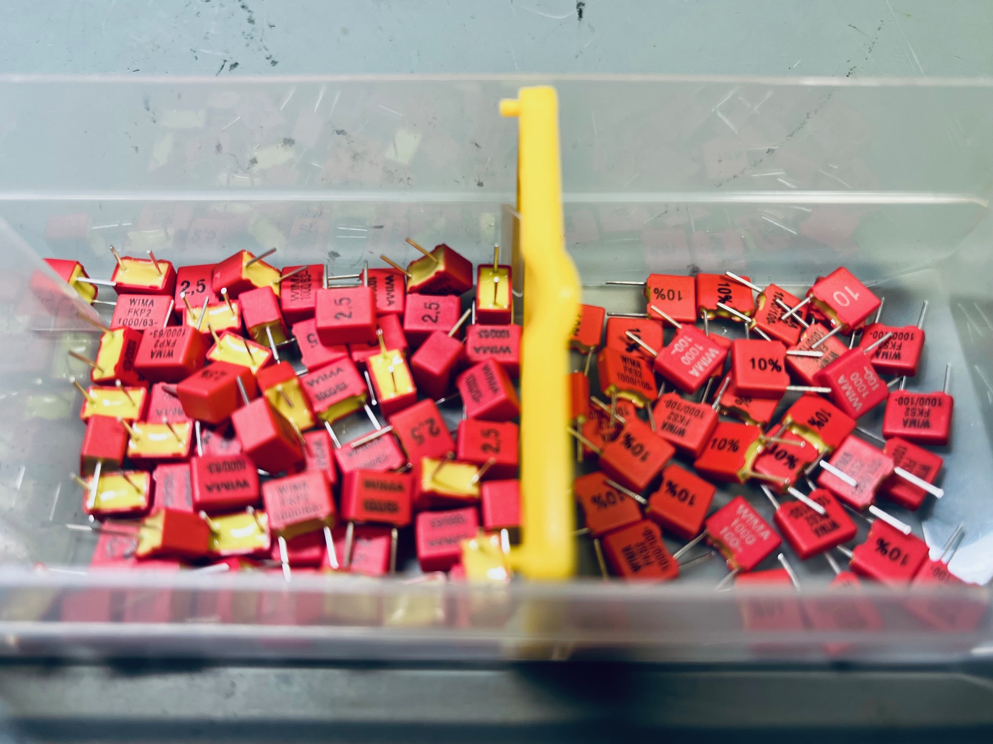
Film capacitors sit between ceramic and electrolytic types in terms of capacitance and are prized for their stability, accuracy, and low distortion. They are often used in:
- audio signal paths
- filters
- timing-critical circuits
Common film capacitor types include polyester (Mylar) and polypropylene. Values typically range from a few hundred picofarads up to several microfarads.
Film capacitors are:
- non-polarized (orientation does not matter)
- available with tighter tolerances (often 1%–10%)
- physically larger than ceramics at the same value
Their capacitance value is often printed in pF, nF, or µF, sometimes along with the voltage rating. Because of their stability, film capacitors are a common choice wherever predictable behavior is important, such as in VCOs and filters.
1000 = 1000pF = 1nF
0.1  = 0.1µF  = 100nF
2n2  = 2.2nF
Resistors#
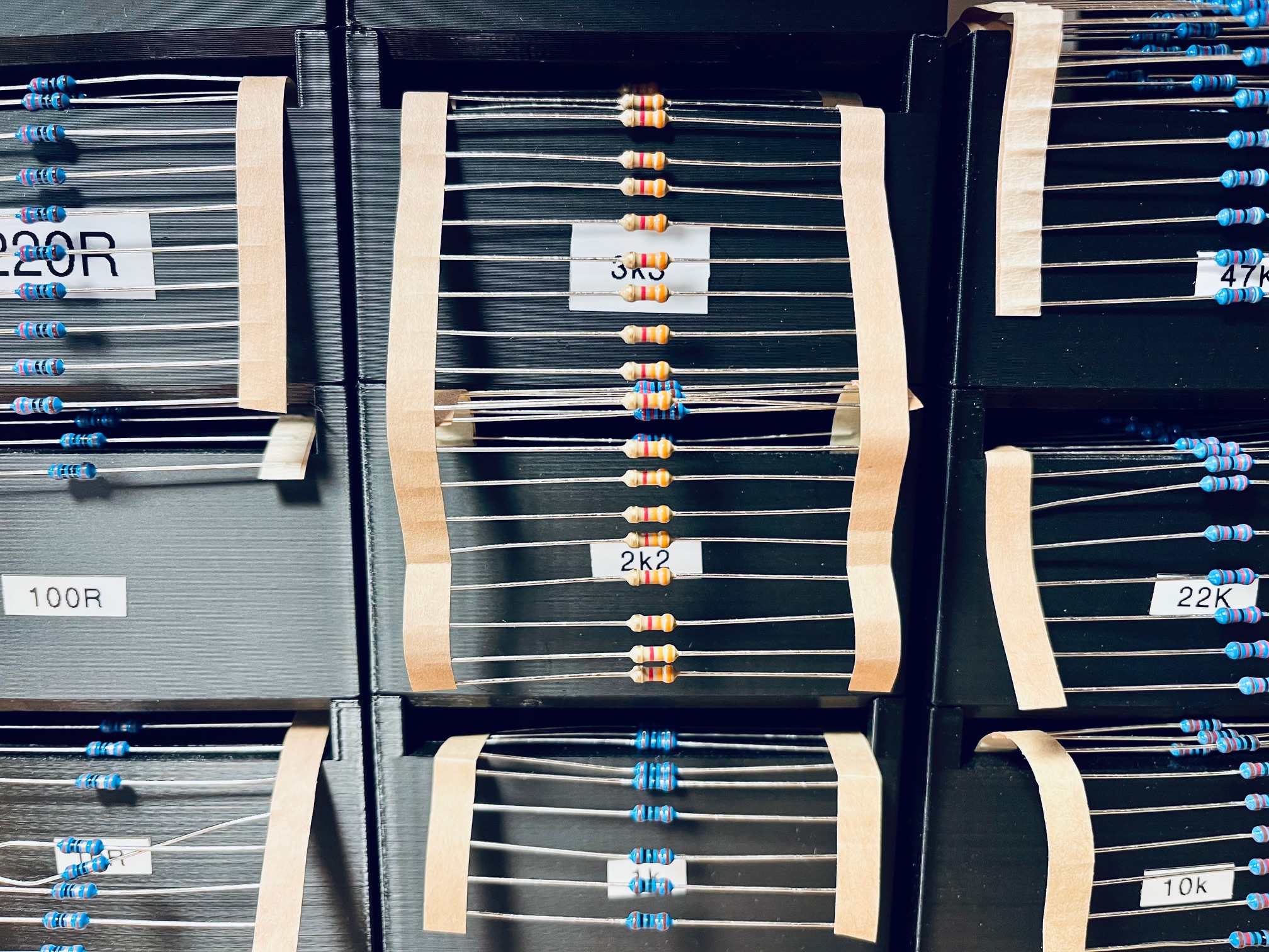
Resistors come in many packages and power ratings. I usually use through-hole DIN0207 resistors (L = 6.3 mm, D = 2.5 mm) with a 1% tolerance, 0.6W load. In the BOM resistors are usually outlined with an R, values are written like:
100 = 100R = 100Ω = 100 ohms
10k = 10kΩ = 10 kilo ohms = 10000 ohms
2k2 = 2.2kΩ = 2.2 kilo ohms = 2200 ohms
1M  = 1MΩ = 1 mega ohm = 1000000 ohms
2M2 = 2.2MΩ = 2.2 mega ohms = 2200000 ohms
...
There are resistor series with preferred numbers of resistor values called E-series. I usually use resistors from the E24 series. The resistance value is encoded using color bands, which indicate:
- resistance value
- multiplier
- tolerance
- (optionally) temperature coefficient
You’ll encounter resistors with:
- 4 bands (value, multiplier, tolerance)
- 5 bands (higher precision, common for 1%)
- 6 bands (adds temperature coefficient)
💡 Tip: When in doubt—especially if colors are hard to distinguish—use a multimeter to measure the resistance directly.
The interactive tool below lets you decode resistor color bands:
Resistor Color Code Dial#
LEDs#
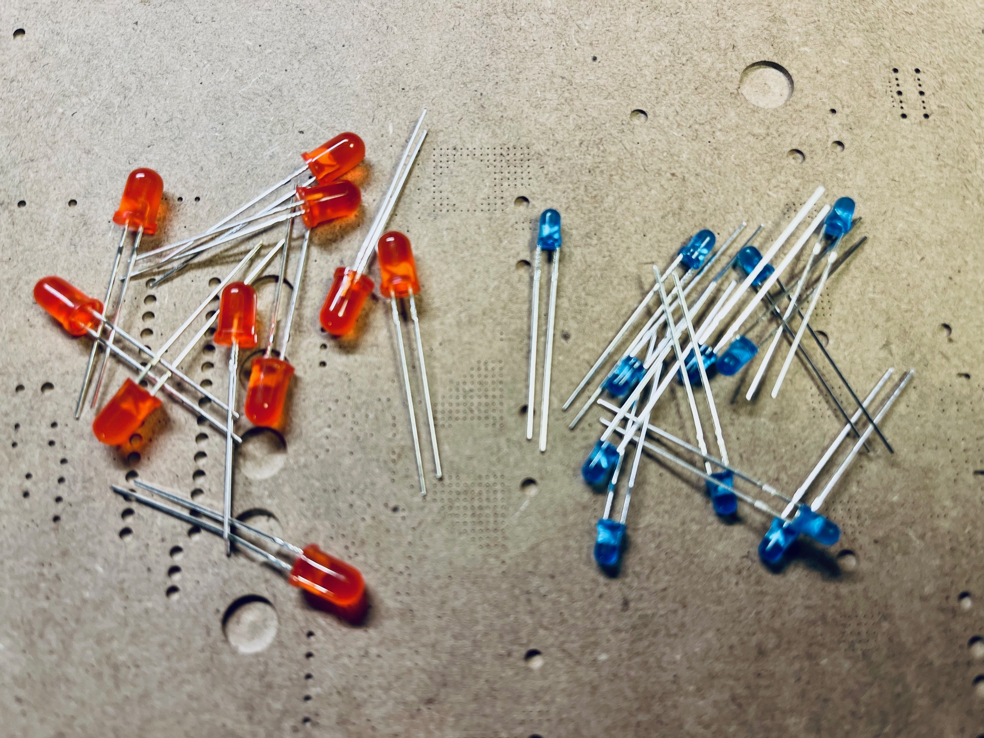
Through-hole LEDs commonly come in 3 mm and 5 mm diameters, with a wide range of colors and brightness levels.
LEDs are polarized components, so orientation matters:
- the flat edge of the LED marks the negative terminal (cathode)
- the longer leg is usually the positive terminal (anode)
Some modules use bi-color (bi-polar) LEDs. In these, the displayed color depends on the polarity of the applied voltage. For example, in my LFO module the LED changes color depending on the direction of the modulation. Make sure to use a resistor for current limiting (usually 20mA) when powering a LED, e.g.
12V / 0.02A = 600Ω (use next higher values like 680Ω or 1kΩ)
Connectors#
Connectors are used to bring power, signals, and control voltages in and out of a module, or to link PCBs together. Choosing the correct connector type is essential for both functionality and compatibility.
IDC (10/16-pin)#
IDC (Insulation Displacement Connector) ribbon cables are the standard power connectors in Eurorack systems. They are typically found in 10-pin or 16-pin variants:
- 10-pin: power only
- 16-pin: power plus additional signals (
+5V, CV, gate)
The red stripe on the ribbon cable marks -12V. On PCBs, this is usually indicated with a -12V, a stripe, or the label RED.
⚠️ Always double-check orientation before powering up a module. Reversed power cables are a common cause of damaged ICs.
Pin Headers / Sockets#
Pin headers and sockets are simple connectors made of individual metal pins arranged in a row. They are commonly used for:
- board-to-board connections
- panel wiring (LEDs, switches, jacks)
- jumpers and configuration options
Pin headers can be:
- male (pins)
- female (sockets)
- straight or angled
They are specified by pin count and pitch, most commonly 2.54 mm.
Thonkiconn Jacks (Mono / Stereo)#
Thonkiconn-style 3.5 mm jacks are the de facto standard audio and CV connectors in Eurorack modules.
- Mono (TS, black) jacks are used for most CV and audio signals
- Stereo (TRS, green) jacks are often used for audio signals and MIDI
They are PCB-mounted, compact, and designed specifically for Eurorack panel spacing.
When wiring or placing them on a PCB, pay attention to:
- tip, ring, and sleeve pinout
- switched vs non-switched contacts
Mono (TS) Jack Pinout#
A mono jack has three functional connections:
- Tip – signal
- Sleeve – ground
- Switch – connected to the tip when no plug is inserted (used for normalization)
Stereo (TRS) Jack Pinout#
A stereo jack adds a second signal and has no switched contact:
- Tip – left channel / primary signal
- Ring – right channel / secondary signal
- Sleeve – ground
Stereo jacks are commonly used in Eurorack for:
- Stereo headphones
- MIDI
Integrated Circuits (ICs)#
Integrated circuits combine many electronic components into a single package. In synth DIY, ICs handle amplification, logic, timing, and signal processing tasks.
Most ICs used in DIY synths are through-hole DIP packages, which are beginner-friendly and easy to replace.
Op-Amps (TL072, TL074, NE5532)#
Operational amplifiers (op-amps) are among the most important ICs in analog synthesizers. They are used for:
- signal amplification
- buffering
- mixing
- filtering
Common types:
- TL072 – dual op-amp, low noise, JFET input, very common in Eurorack
- TL074 – quad version of the TL072
- NE5532 – dual op-amp, very low noise, higher current draw
Op-amps are polarized components. Pin 1 is marked by a dot or notch on the package and must align with the PCB marking.
Using IC sockets is strongly recommended. They protect the IC from heat damage and make replacements easy.
555 Timer#
The 555 timer is a classic and versatile IC used for:
- clocks
- LFOs
- envelope generators
- simple oscillators
It can operate in different modes (astable, monostable, bistable), making it ideal for timing-related circuits.
Like op-amps, the 555 is polarized and must be aligned correctly with the PCB footprint.
40xx CMOS#
The 40xx series CMOS logic ICs provide digital building blocks such as:
- gates (AND, OR, XOR)
- flip-flops
- counters
- multiplexers
Common examples include:
- 40106 – hex Schmitt trigger inverter (great for oscillators)
- 4016/4066 – quad bilateral switch
- 4017 – decade counter
- 4024 – 7-stage binary counter
- 4051 – analog multiplexer
CMOS ICs are sensitive to static electricity. Avoid touching the pins directly and store them in anti-static packaging when possible.
Linear Voltage Regulators#
Linear voltage regulators are used to step down a given voltage to ±12V needed for Eurorack. The 78xx and 79xx series are the most common regulators to power DIY synth modules.
- 78xx series (positive regulators) – step down to lower positive voltages
- 7805 – outputs +5V (common for digital ICs)
- 7809 – outputs +9V
- 7812 – outputs +12V (regulation/cleanup of the +12V rail)
- 79xx series (negative regulators) – step down to lower negative voltages
- 7905 – outputs -5V
- 7909 – outputs -9V
- 7912 – outputs -12V (regulation/cleanup of the -12V rail)
These regulators are used to:
- step down a given voltage
- provide clean, regulated power
- filter and stabilize noisy power rails
Linear regulators dissipate excess voltage as heat. For higher current applications, they may require heat sinks.
Take a look at my Eurorack power supply for a typical application.
Potentiometers#
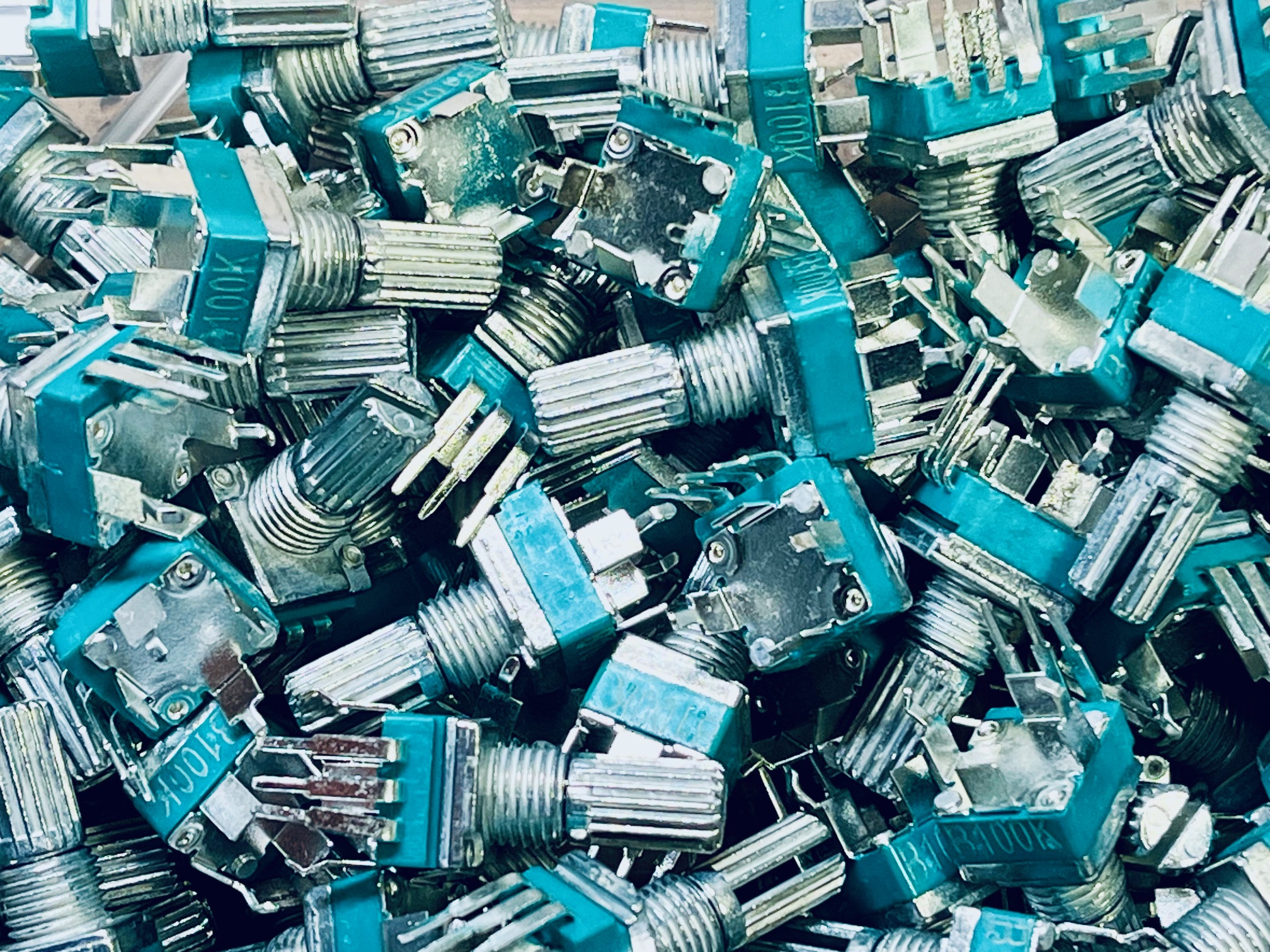
Potentiometers (pots) are variable resistors used as knobs. In synth modules they control parameters like frequency, level, and modulation depth.
They are specified by:
- resistance value (e.g.
100k) - taper (linear
B, logarithmicA) - mechanical size and shaft type
In Eurorack, the most common brands are Alpha and ALPS.
Vertical Alpha / ALPS Pots#
Vertical PCB-mounted Alpha or ALPS potentiometers are widely used in DIY kits because they:
- align directly with the front panel
- reduce wiring
- are mechanically stable
Typical specifications:
- 9 mm or 16 mm body size
- 6.35 mm (1/4") or 6 mm shaft
- knurled or D-shaft
Always match the pot footprint to the PCB and the shaft type to your knobs.
Trimpots#
Trimpots are small adjustable potentiometers mounted directly on the PCB. They are used for:
- calibration
- offset adjustment
- fine-tuning internal parameters
They are adjusted with a small screwdriver and are not meant for frequent user interaction.
Precision Trimmers#
Precision trimmers are higher-quality trimpots designed for stable and accurate adjustments. They are often used for:
- V/oct calibration
- tuning stability
- critical reference voltages
Compared to standard trimpots, they offer smoother adjustment and better long-term stability, often with multi-turn mechanisms.
Transistors#
Transistors are active semiconductor components used for amplification, switching, buffering, and current control. In analog synthesizers they appear in:
- exponential converters
- output buffers
- envelope and logic circuits
- discrete amplifiers
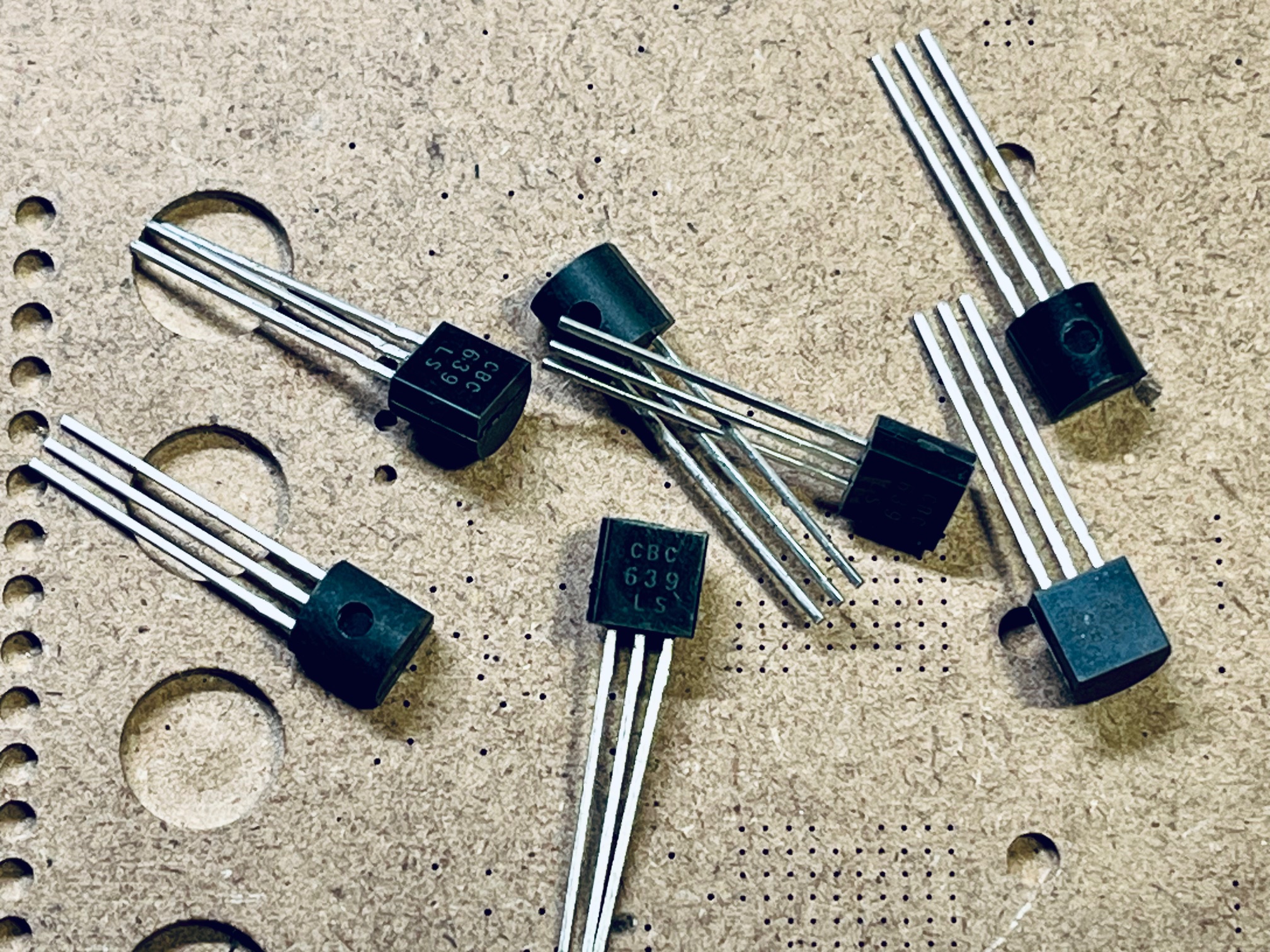
Most transistors in DIY synths are bipolar junction transistors (BJTs) in a TO-92 through-hole package.
NPN / PNP Basics#
BJTs come in two complementary types:
- NPN – conducts when the base is driven positive relative to the emitter
- PNP – conducts when the base is driven negative relative to the emitter
They are often used in pairs for symmetrical circuit behavior.
Common Types#
- 2N3904 – NPN, general-purpose, very common
- 2N3906 – PNP complement to the 2N3904
- BC639 – NPN, higher current capability
- BC640 – PNP complement to the BC639
The pinout matters and varies by transistor family. Always check the datasheet and match it to the PCB silkscreen.
Diodes#
Diodes allow current to flow in one direction only. In synth circuits they are used for:
- polarity protection
- input protection for microcontrollers
- signal shaping and clipping
- rectification
- logic and switching
Diodes are polarized components, so orientation is critical.
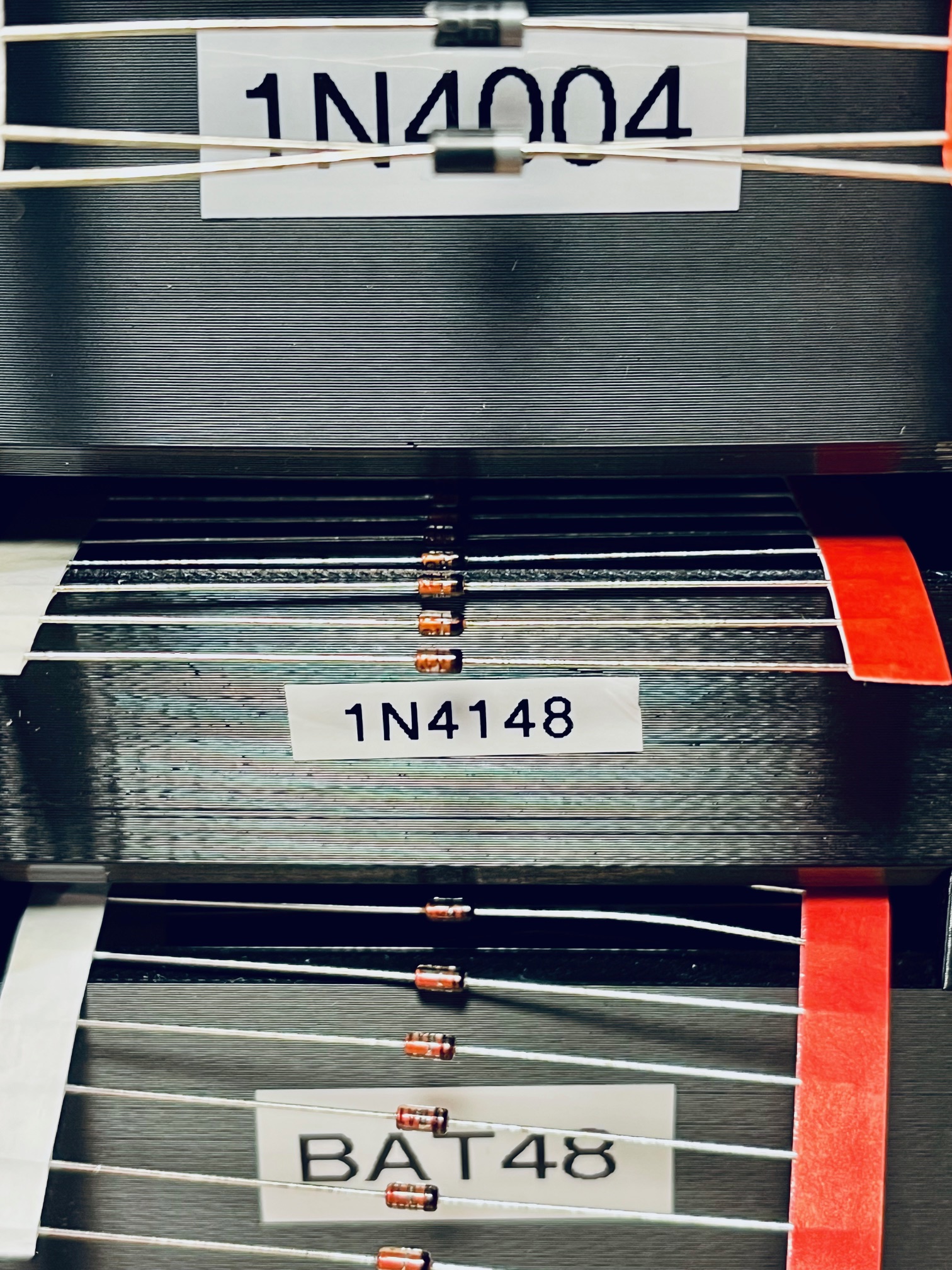
Common Types#
- 1N4148 – fast switching silicon diode, very common in signal paths
- BAT48 – Schottky diode, low forward voltage drop
- 1N4004 – rectifier diode, used in power supplies
Forward Voltage (Vf)#
An important diode characteristic is the forward voltage (Vf) — the voltage drop across the diode when it is conducting. It is the amount of voltage needed to get current to flow across a diode.
Typical values for Vf:
- 1N4148 (silicon): ~0.6–1.0V
- BAT48 (Schottky): ~0.2–0.3V
- 1N4004 (silicon rectifier): ~0.7–1.1 V
In synth circuits this matters because:
- lower Vf diodes (Schottky) clip signals earlier
- higher Vf diodes are better for power protection
- diode choice affects waveform shaping and distortion
The cathode is marked with a stripe on the diode body and corresponds to the line in the schematic symbol.