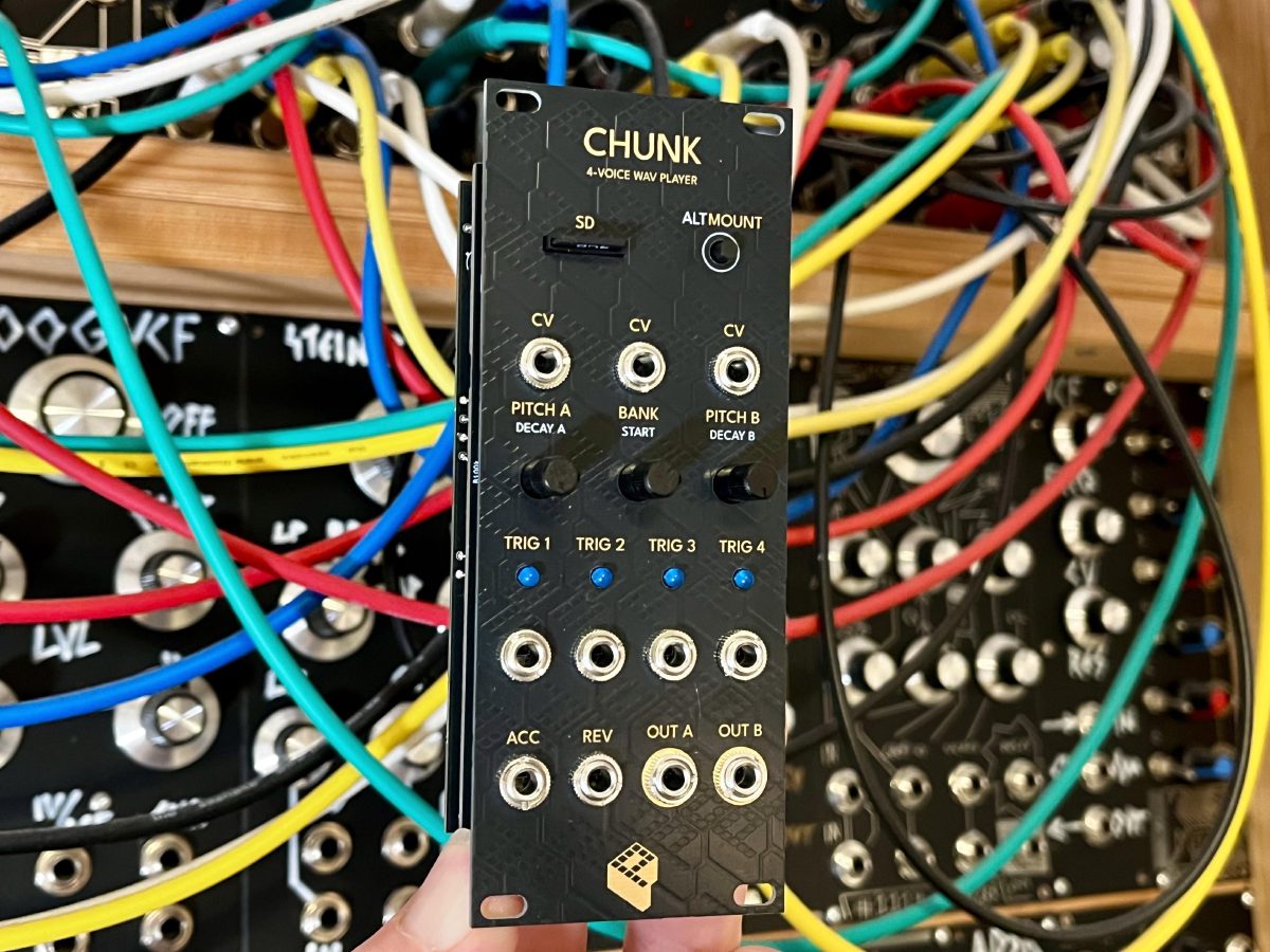
CHUNK plays your own WAV samples from a microSD card. Four trigger inputs fire four voices, each with its own sample, and two gate inputs add accent and reverse playback to every hit. The samples are organised in ten banks that you can switch by knob or CV. A second layer of controls behind the ALT button sets the decay and the start point of the samples. The module is built around a Raspberry Pi Pico 2 and a PCM5102A audio DAC, and the firmware is open-source, so you can adapt it to your own ideas.
The name comes from the WAV file format: a WAV file is a RIFF container made of chunks, and the audio itself lives in the data chunk.
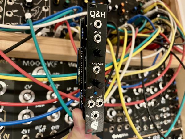
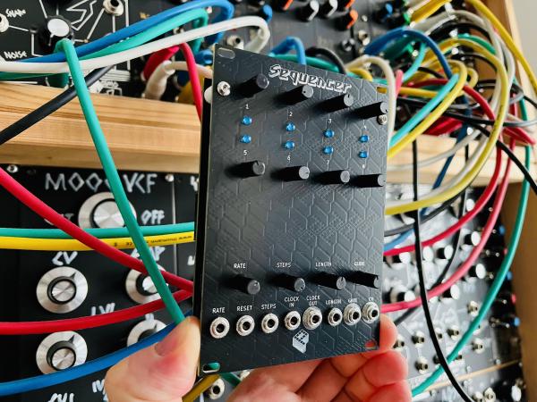
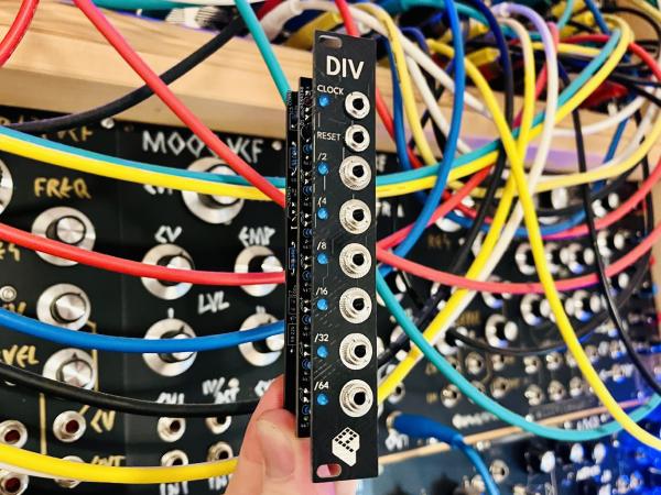
Perfect companion for the Sequencer and the Clock Divider.
Buy kit or PCBs in my storeKey features#
- 4 voices, one sample per trigger input
- Samples from a microSD card, 10 banks of 4 samples
- Bank select by knob, also per CV
- Pitch control for voices 1+2 and 3+4 (0.5× to 2×, one octave each way), also per CV
- Accent gate input (+6 dB) and reverse gate input, sampled with every trigger
- ALT layer: decay for voices 1+2 and 3+4, sample start point
- CV inputs
0-3.3V, attenuated by the knob - Trigger LEDs
- Two audio outputs: voices 1+2 on OUT A, voices 3+4 on OUT B, about
8.6Vppfull scale - Low latency: samples start from RAM, without waiting for the SD card
- Raspberry Pi Pico 2 (RP2350), open-source firmware
- PCM5102A 32-bit stereo audio DAC, pre-soldered on the PCB together with its three capacitors
- Black front panel with ENIG gold-plated lettering and logo
- 10HP wide
Controls#
| Control | Normal | Hold ALT and turn |
|---|---|---|
| PITCH A | Pitch of voices 1+2 | DECAY A |
| BANK | Sample bank 1–10 | START |
| PITCH B | Pitch of voices 3+4 | DECAY B |
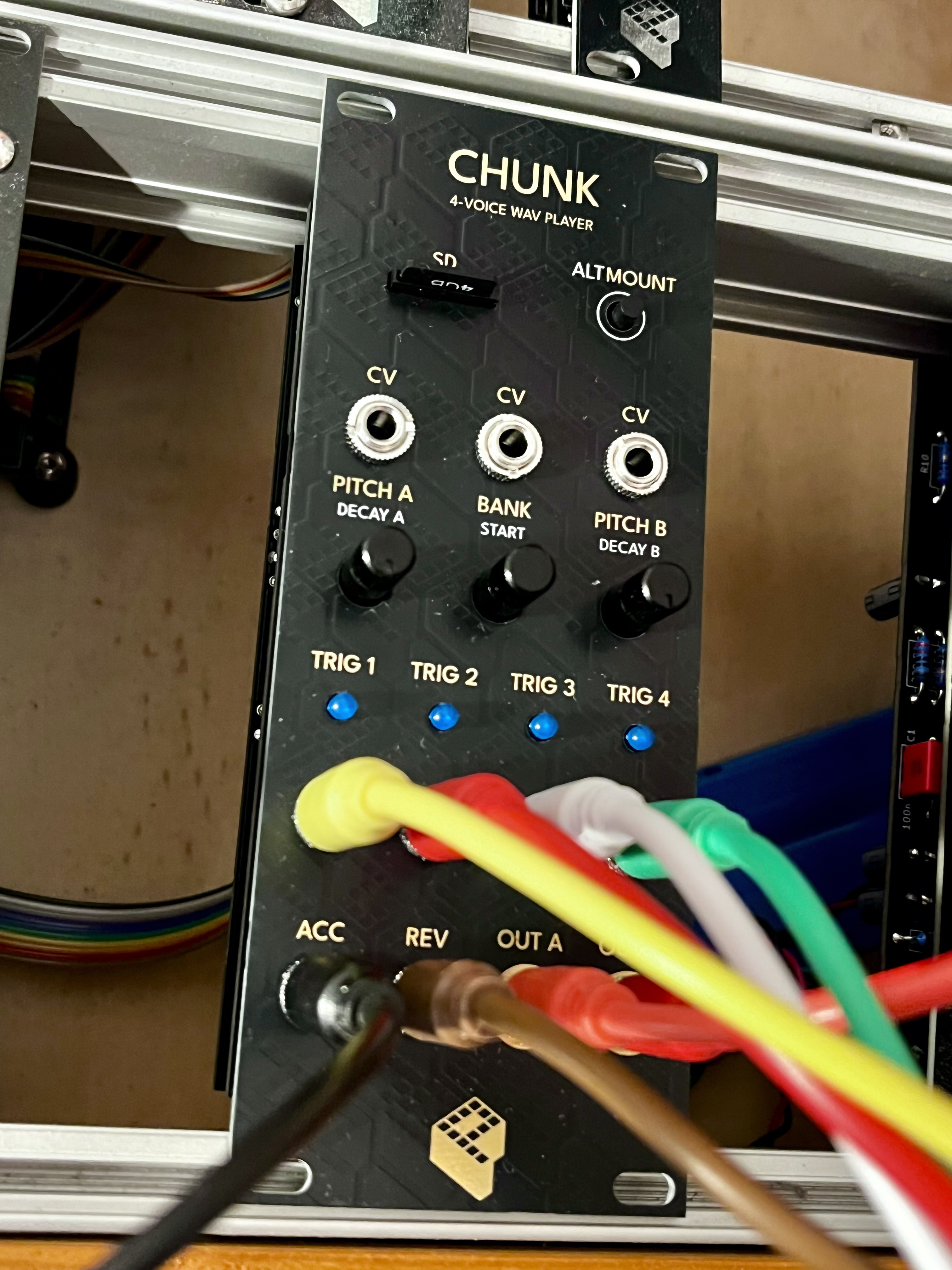
The gold labels on the front panel show the normal functions, the white labels the ALT functions.
| Jack | Function |
|---|---|
| TRIG 1–4 | Trigger inputs, one per voice |
| ACC | Accent: a hit is played +6dB louder when this gate is high at the moment of the trigger |
| REV | Reverse: a hit is played backwards when this gate is high at the moment of the trigger |
| CV (3×) | Control voltage for PITCH A, BANK and PITCH B, 0-3.3V. With a cable plugged in, the knob attenuates the CV; higher voltages are clipped at 3.3V, negative voltages read as 0V |
| OUT A | Audio output, voices 1+2 |
| OUT B | Audio output, voices 3+4 |
ALT/MOUNT button:
- Hold and turn a knob: edits the ALT function of that knob. The four LEDs show the value as a bar, more LEDs for a longer sound: for DECAY the decay time, for START how much of the sample is left to play (all on = from the beginning).
- Hold for 2 seconds without turning a knob: re-mounts the SD card, for example after swapping it. The LEDs count up while you hold the button. All LEDs off afterwards means the card was mounted; three blinks mean no card was found.
DECAY fades each hit out exponentially, from very short clicks to about three seconds. Turned fully clockwise, decay is off and every sample plays to its end. START skips into the sample, so you can cut off the attack or play only the tail of a sound. With the REV gate high, START skips from the end of the sample instead.
When the bank changes, the LEDs show the new bank number for a moment, in binary: LED 1 counts 1, LED 2 counts 2, LED 3 counts 4 and LED 4 counts 8. Bank 3 lights LEDs 1 and 2, bank 10 lights LEDs 2 and 4.
When you press or release ALT, the knobs use pickup: a knob only takes over a value once you turn it to (or across) its stored position. Nothing jumps when you switch between the layers.
How it works#
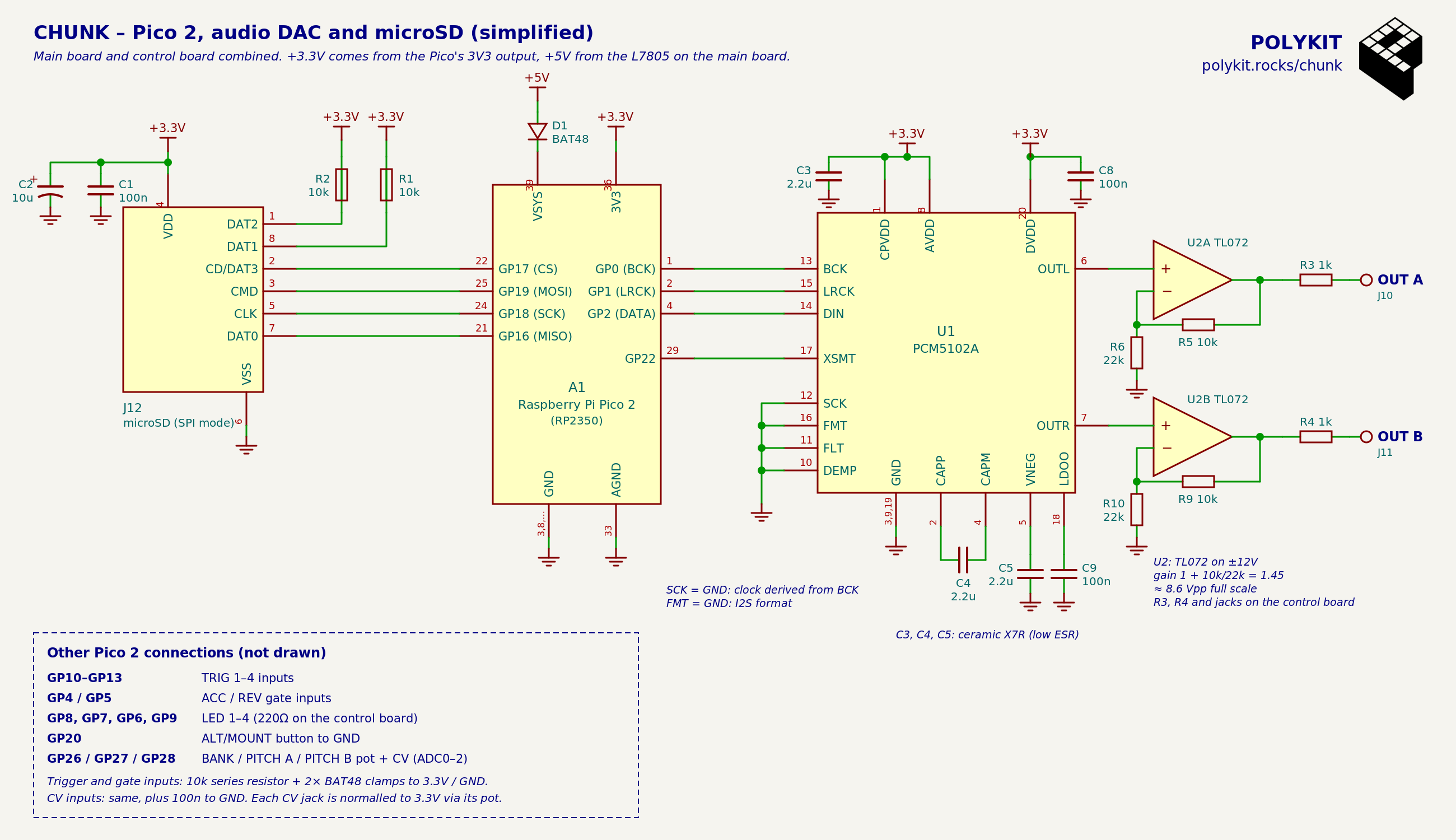
At the heart of the module sits a Raspberry Pi Pico 2. Its dual-core RP2350 microcontroller reads the trigger, gate and button inputs, the three knobs, and streams the samples from the microSD card.
The work is split between the two cores. The first core polls the inputs and mixes the four voices into a stereo audio stream. The second core handles the SD card. For every voice it keeps the current bank’s file open and holds the first and last ~0.3 seconds of the sample in RAM. When a trigger arrives, the voice starts playing from this cache right away, so there is no waiting for the card. Short drum hits play entirely from RAM. For longer samples, the second core streams the rest from the card in the background, always serving the voice with the least audio buffered first.
Pitch is changed by playing the sample faster or slower, with linear interpolation between the sample values. The audio is sent via I2S to a PCM5102A DAC. This DAC has an internal charge pump, so its outputs swing around ground without a DC offset. A TL072 op-amp amplifies the signal by 1.45 to about 8.6Vpp at full scale. 1k resistors protect the outputs.
All trigger and gate inputs are protected with a 10k series resistor and two BAT48 Schottky diodes that clamp the voltage to the Pico’s 3.3V range. A gate counts as high above about 2V. The CV inputs use the same protection plus a 100n filter capacitor. Each CV jack is normalled to 3.3V, so with nothing plugged in, the knob sets the value directly. With a cable plugged in, the knob attenuates the CV.
The module is powered from +12V (an L7805 regulator supplies the Pico); the TL072 runs on ±12V.
Build Guide#
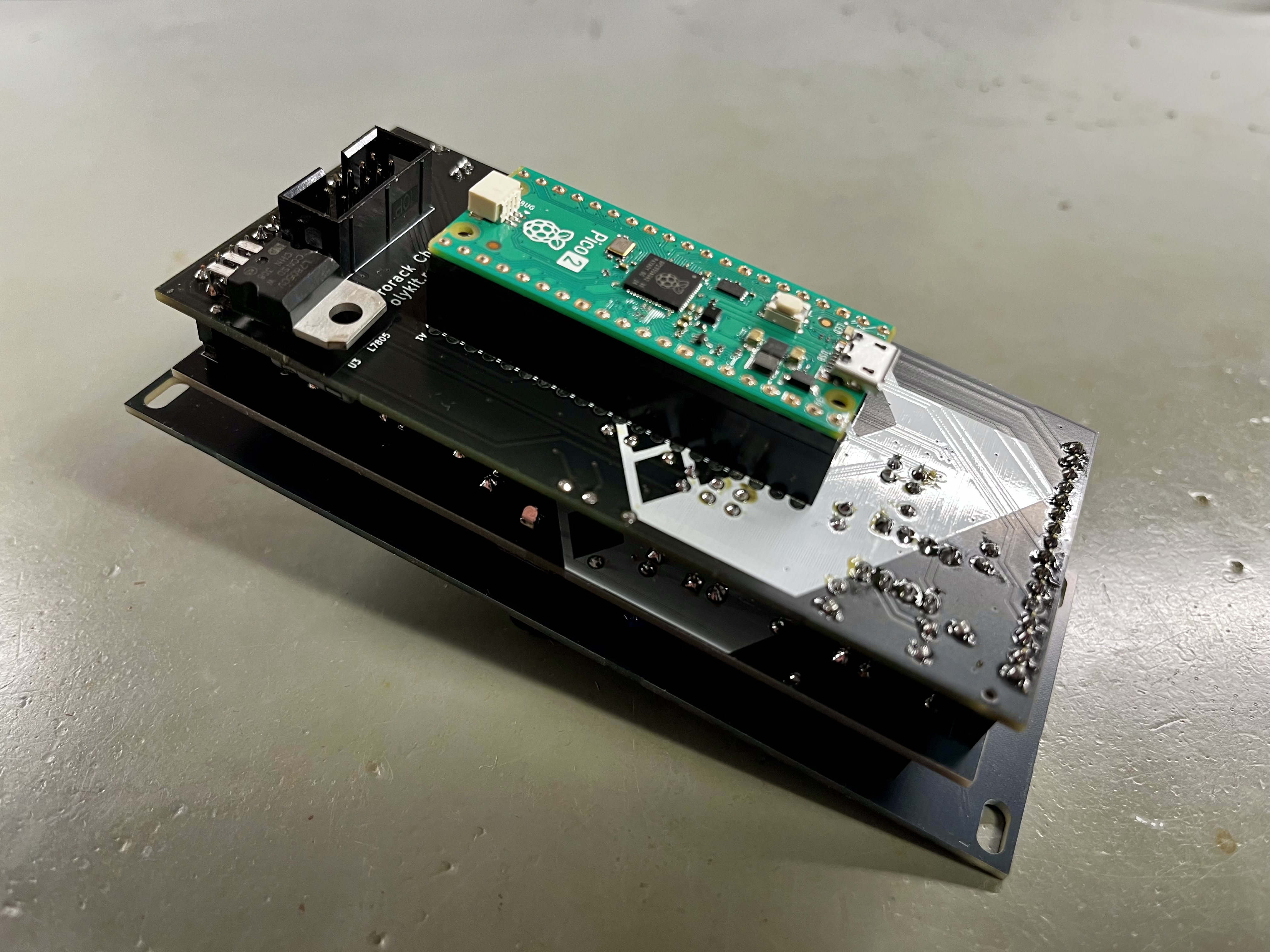
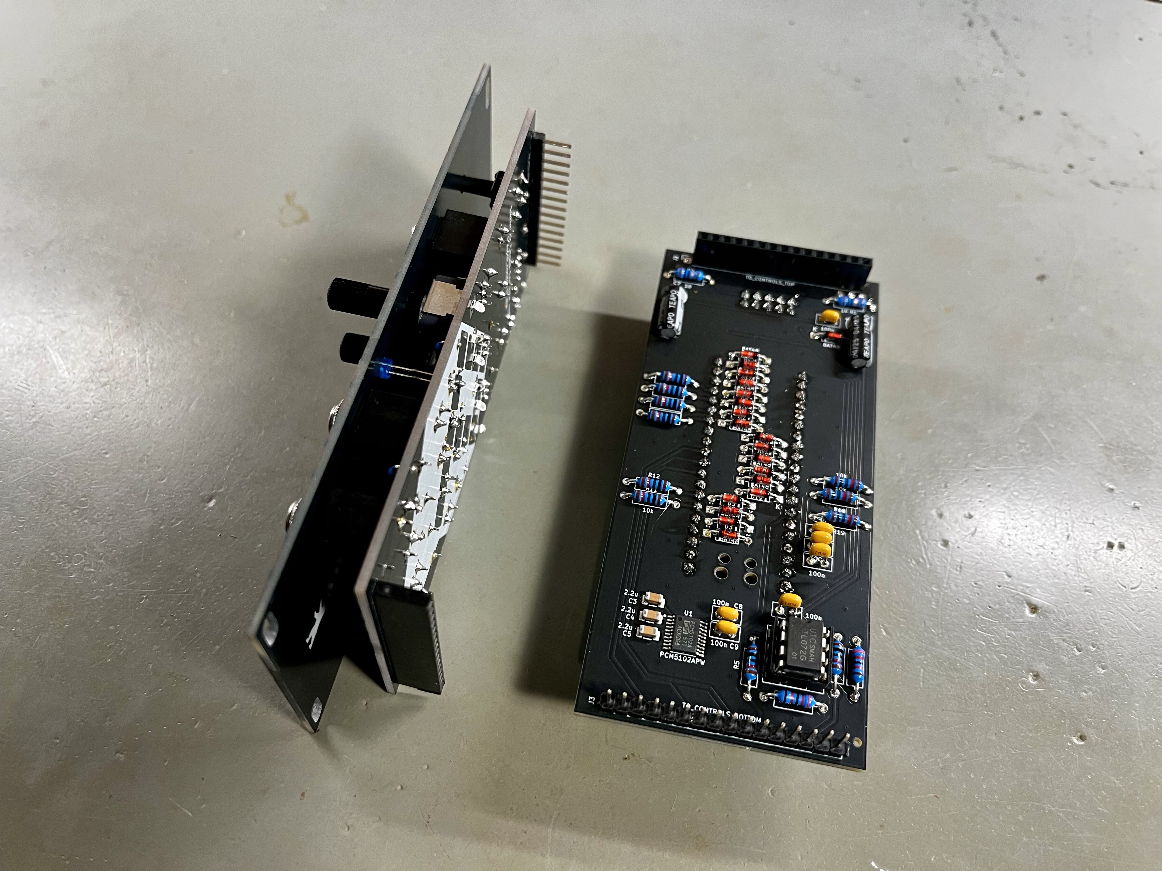
The build is straightforward and well-suited for anyone with basic soldering experience. The only surface-mount parts, the PCM5102A DAC and its three capacitors, come pre-soldered on the main board. Everything else is through-hole. The design consists of three PCBs: the front panel, a control/jack board, and the main circuit board.
Start by populating the main circuit board. Begin with the lowest-profile components (resistors, diodes, small capacitors) and work your way up to taller parts like electrolytic capacitors, the IC socket and the voltage regulator. The Raspberry Pi Pico 2 and the 10-pin power connector go on the back side of the main board.
On the control board, the pin headers go on the back side. Leave the LEDs, jacks, potentiometers, the button and the SD card socket for last.
When mounting the LEDs, jacks, potentiometers, the button and the SD card socket, first place them on the board, then align and secure the front panel before soldering. This ensures proper mechanical alignment and a clean fit. The potentiometers have no threaded bushing; the front panel is held by the jack nuts.
Once all components are soldered, insert the TL072 into its socket — pay close attention to orientation and match the notch on the IC to the marking on the silkscreen.
With the boards fully populated, stack them together using the pin header and socket connections labelled J2/J13 and J3/J14. Ensure that all pins are properly aligned before pressing the boards together to avoid bent pins or poor connections.
Each component location is clearly labelled with its designator and value on the PCB silkscreen. Refer to the BOM below for additional details on component types and values.
See the Component Basics guide for help identifying parts.
First Power-On Check#
Before powering the module for the first time, carefully inspect all components, solder joints, and IC orientations.
Check for potential short circuits using a multimeter between -12V, +12V, and ground. For the initial test, it’s best to connect the module to the power supply alone and verify proper operation. Without an SD card, the four LEDs blink three times after power-on.
SD card#
CHUNK needs a microSDHC card with 4 to 32 GB, formatted with FAT32. Capacity and speed class don’t matter, the sample library needs only a few megabytes. Cards with 2 GB or less (SDSC) and with 64 GB or more (SDXC, formatted with exFAT) are not supported.
New microSDHC cards come formatted with FAT32. If you need to format a card yourself, choose FAT32 (on macOS: MS-DOS (FAT) with the Master Boot Record scheme, on Linux: sudo mkfs.vfat -F 32 /dev/sdX1).
The card goes into the slot in the front panel. To swap it while the module is running, insert the new card and hold the ALT/MOUNT button for two seconds.
Sample library#
CHUNK comes with a sample library of 10 banks, ready to play. All samples are loudness-matched, start right on the hit, and are free to use in your music, royalty-free.
Download the sample library (ZIP, 2.9 MB)
Unzip it to the root of the SD card, so that the card contains the samples folder and the README.TXT. The README lists every sound.
| Bank | Content | TRIG 1 / 2 (OUT A) | TRIG 3 / 4 (OUT B) |
|---|---|---|---|
| 1 | Analog kit, 808-style | kick, snare | closed hat, clap |
| 2 | Digital kit, 707-style with 6-bit cymbals | kick, snare | hat, crash |
| 3 | Oberheim DX | kick, snare | closed hat, clap |
| 4 | Sequential DrumTraks | kick, snare | closed hat, open hat |
| 5 | Vintage toms & percussion | low tom, high tom | cowbell, crash |
| 6 | Analog percussion, 808-style | low conga, high conga | cowbell, clave |
| 7 | FM metal | bell, FM tom | gong, zap |
| 8 | Plucks & mallets, tuned to C | bass pluck, pluck | marimba, kalimba |
| 9 | Casio toys (PT-1, PT-20) | piano, violin | C chord, Am chord |
| 10 | Casio PT-1 rhythm loops | rock, bossa nova | samba, swing |
Banks 1, 2, 6, 7 and 8 are synthesized from scratch. The drum machine and Casio sounds are my own recordings from the polykit sample library. Bank 8 is tuned to C, so the PITCH knobs play it like an instrument. In bank 10, every trigger starts a one-bar rhythm loop: PITCH changes its tempo, DECAY fades it out and REV plays it backwards.
Preparing samples#
The samples go into one folder per bank:
samples/
  bank1/
    t1.wav   (TRIG 1)
    t2.wav   (TRIG 2)
    t3.wav   (TRIG 3)
    t4.wav   (TRIG 4)
  bank2/
    ...
  bank10/
The samples must be 16-bit PCM, mono, 44.1 kHz. Other sample rates play at the wrong pitch. For the best results, normalize the samples to around -3dBFS and trim any silence at the start, so the hit sounds right on the trigger. With ffmpeg a sample can be converted like this:
ffmpeg -i input.wav -ac 1 -ar 44100 -c:a pcm_s16le -map_metadata -1 t1.wav
Samples can be of any length. Banks don’t need to be complete: a missing file just leaves that voice silent. The names are fixed: CHUNK looks for exactly t1.wav to t4.wav in the folders bank1 to bank10 inside samples, other files are ignored. Upper or lower case doesn’t matter.
Software#
CHUNK runs on open-source firmware written in C with the Raspberry Pi Pico SDK. You’re free to modify, extend, or completely rebuild the code to suit your own ideas.
The source code will be published on GitHub soon.
To update the firmware, hold the BOOTSEL button on the Pico while connecting it to your computer via USB. The Pico shows up as a USB drive; copy the .uf2 firmware file onto it and it restarts with the new firmware. Disconnect the module from the Eurorack power supply while the Pico is connected via USB.
Each kit comes with a Pico 2 pre-flashed with the standard firmware, so you can get started right away — no programming required unless you want to customize it.
BOM#
Link to interactive BOM of the component board
| Reference | Value | Footprint | Qty | Description |
|---|---|---|---|---|
| A1 | Raspberry Pi Pico 2 | Raspberry Pi Pico:RaspberryPi_Pico_Common | 1 | Raspberry Pi Pico 2 (RP2350) |
| C1,C2,C8,C9,C10,C11,C12 | 100n | Capacitor_THT:C_Disc_D5.0mm_W2.5mm_P2.50mm | 7 | Ceramic |
| C3,C4,C5 | 2.2u | Capacitor_SMD:C_1206_3216Metric | 3 | Ceramic X7R, 1206, pre-soldered |
| C6,C7 | 10u | Capacitor_THT:CP_Radial_D5.0mm_P2.50mm | 2 | Electrolytic |
| D1, D2, D3, D4, D5, D6, D7, D8, D9, D10, D11, D12, D13, D14, D15, D16, D17, D18, D19 | BAT48 | Diode_THT:D_DO-35_SOD27_P7.62mm_Horizontal | 19 | Schottky diode, DO-35 |
| J2, J3 | Conn_01x16 | Connector_PinSocket_2.54mm:PinSocket_1x16_P2.54mm_Vertical | 2 | 16-pin socket, 2.54mm |
| POWER1 | Conn_02x05_Odd_Even | Connector_IDC:IDC-Header_2x05_P2.54mm_Vertical | 1 | IDC 10-pin power connector |
| R1,R2 | 10 | Resistor_THT:R_Axial_DIN0207_L6.3mm_D2.5mm_P10.16mm_Horizontal | 2 | 1/4W 1% resistor |
| R5,R9,R11,R12,R13,R14,R15,R16,R17,R18,R19 | 10k | Resistor_THT:R_Axial_DIN0207_L6.3mm_D2.5mm_P10.16mm_Horizontal | 11 | 1/4W 1% resistor |
| R6,R10 | 22k | Resistor_THT:R_Axial_DIN0207_L6.3mm_D2.5mm_P10.16mm_Horizontal | 2 | 1/4W 1% resistor |
| U1 | PCM5102A | Package_SO:TSSOP-20_4.4x6.5mm_P0.65mm | 1 | Stereo audio DAC, TSSOP-20, pre-soldered |
| U2 | TL072 | Package_DIP:DIP-8_W7.62mm_Socket_LongPads | 1 | Dual op-amp, DIP-8 |
| U3 | L7805 | Package_TO_SOT_THT:TO-220-3_Horizontal_TabDown | 1 | 5V voltage regulator, TO-220 |
Link to interactive BOM of the control board
| Reference | Value | Footprint | Qty | Description |
|---|---|---|---|---|
| C1 | 100n | Capacitor_THT:C_Disc_D5.0mm_W2.5mm_P2.50mm | 1 | Ceramic |
| C2 | 10u | Capacitor_THT:CP_Radial_D5.0mm_P2.00mm | 1 | Electrolytic |
| D1, D2, D3, D4 | LED | LED_THT:LED_D3.0mm | 4 | LED, 3mm |
| J1, J2, J3, J4 | TRIG1–4 | Connector_Audio:Jack_3.5mm_QingPu_WQP-PJ398SM_Vertical_CircularHoles | 4 | Mono Thonkiconn 3.5mm jack sockets |
| J5 | ACCENT | Connector_Audio:Jack_3.5mm_QingPu_WQP-PJ398SM_Vertical_CircularHoles | 1 | Mono Thonkiconn 3.5mm jack sockets |
| J6 | REVERSE | Connector_Audio:Jack_3.5mm_QingPu_WQP-PJ398SM_Vertical_CircularHoles | 1 | Mono Thonkiconn 3.5mm jack sockets |
| J7, J8, J9 | CV | Connector_Audio:Jack_3.5mm_QingPu_WQP-PJ398SM_Vertical_CircularHoles | 3 | Mono Thonkiconn 3.5mm jack sockets |
| J10, J11 | OUT | Connector_Audio:Jack_3.5mm_QingPu_WQP-PJ398SM_Vertical_CircularHoles | 2 | Mono Thonkiconn 3.5mm jack sockets |
| J12 | PJS008U-3000-0 | chunk:PJS008U-3000-0_FixPin | 1 | microSD card socket, vertical |
| J13, J14 | Conn_01x16 | Connector_PinHeader_2.54mm:PinHeader_1x16_P2.54mm_Vertical | 2 | 16-pin header, 2.54mm |
| R1,R2 | 10k | Resistor_THT:R_Axial_DIN0207_L6.3mm_D2.5mm_P10.16mm_Horizontal | 2 | 1/4W 1% resistor |
| R3,R4 | 1k | Resistor_THT:R_Axial_DIN0207_L6.3mm_D2.5mm_P10.16mm_Horizontal | 2 | 1/4W 1% resistor |
| R5,R6,R7,R8 | 220 | Resistor_THT:R_Axial_DIN0207_L6.3mm_D2.5mm_P7.62mm_Horizontal | 4 | 1/4W 1% resistor |
| RV1, RV2, RV3 | 100k | Potentiometer_THT:Potentiometer_Alps_RK09K_Single_Vertical | 3 | Linear, mono, vertical, 6mm shaft, no bushing |
| SW1 | ALT/MOUNT | Button_Switch_THT:SW_PUSH_6mm_H13mm | 1 | Tactile switch 6×6mm, 13mm high |
Schematics#
References#
https://www.ti.com/lit/ds/symlink/pcm5102a.pdf
https://datasheets.raspberrypi.com/pico/pico-2-datasheet.pdf
https://datasheets.raspberrypi.com/rp2350/rp2350-datasheet.pdf
https://mm.digikey.com/Volume0/opasdata/d220001/medias/docus/5342/PJS008U-300x-0.pdf